Illuminated Closet Hanging Rods
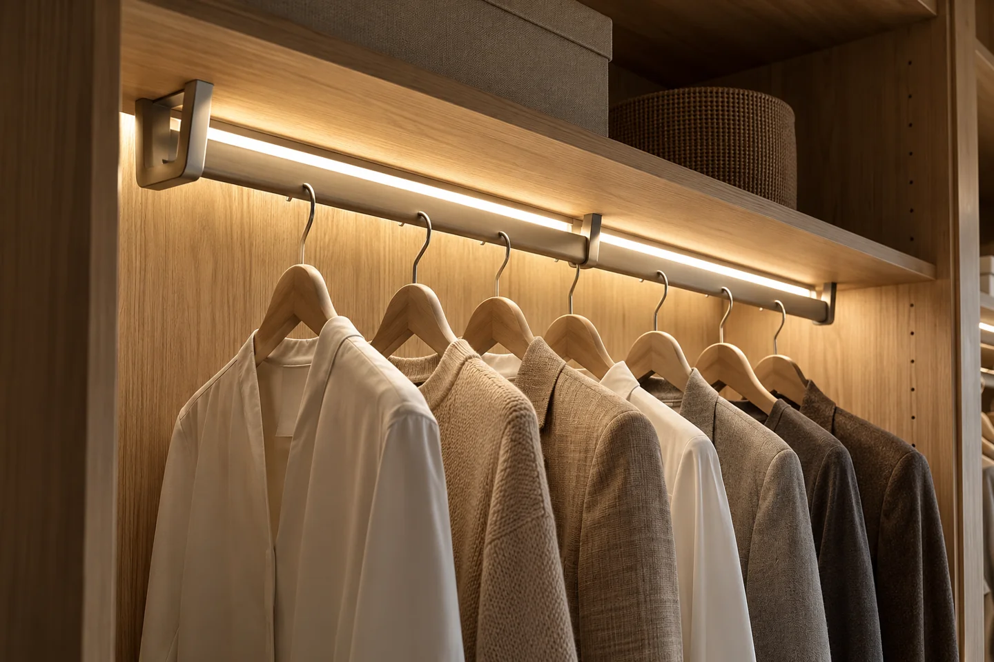
Resolve the structural support and light assembly as one detail; a glowing rail is also part of a loaded furniture component.
View the solution →
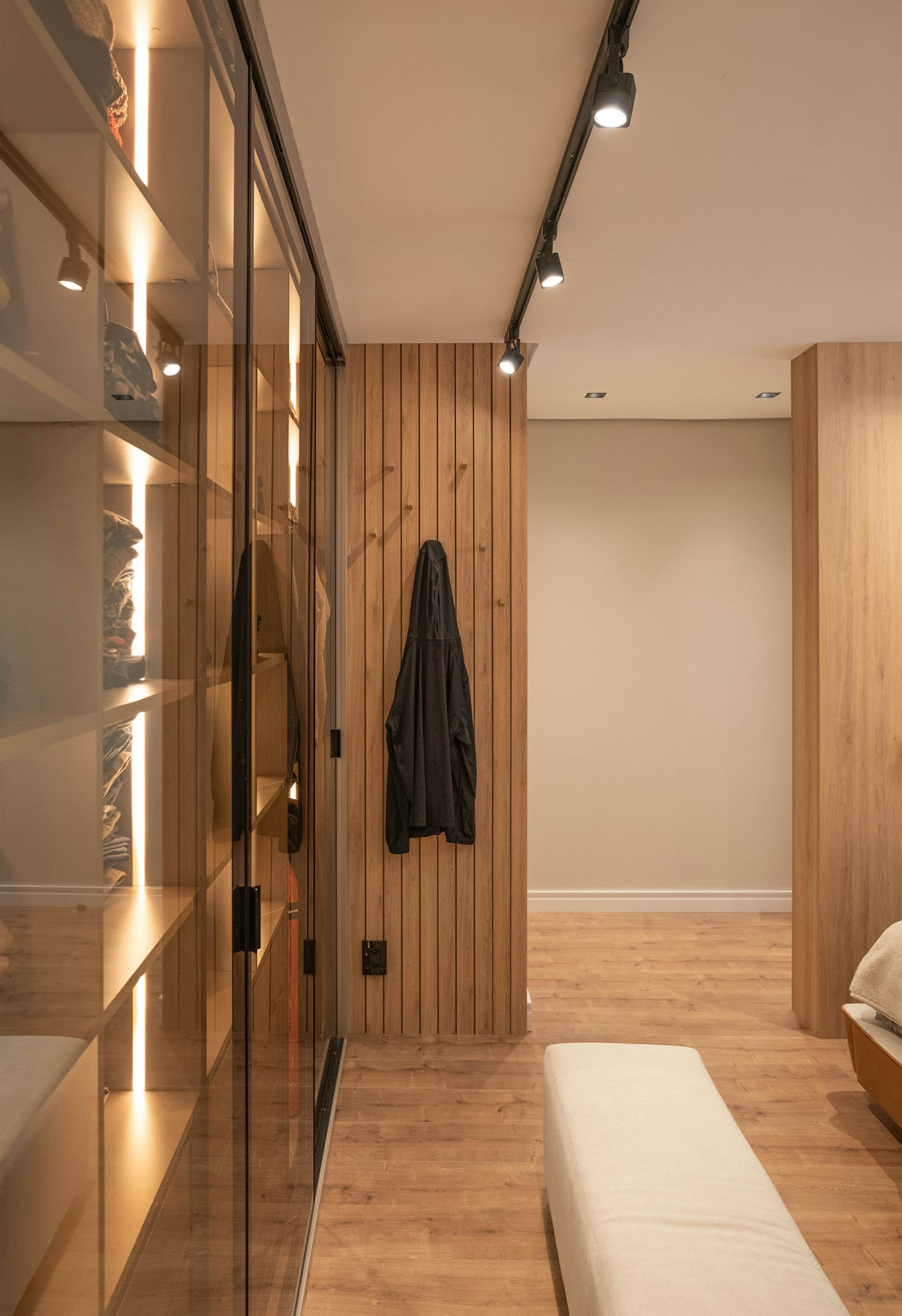
Integrated light for hanging rails, vertical panels and shoe or bag shelves. Match sensing, cable routes and light colour to each compartment.
Discuss this assemblyIntegrated light for hanging rails, vertical panels and shoe or bag shelves. Match sensing, cable routes and light colour to each compartment.
Resolve the structural support and light assembly as one detail; a glowing rail is also part of a loaded furniture component.
View the solution →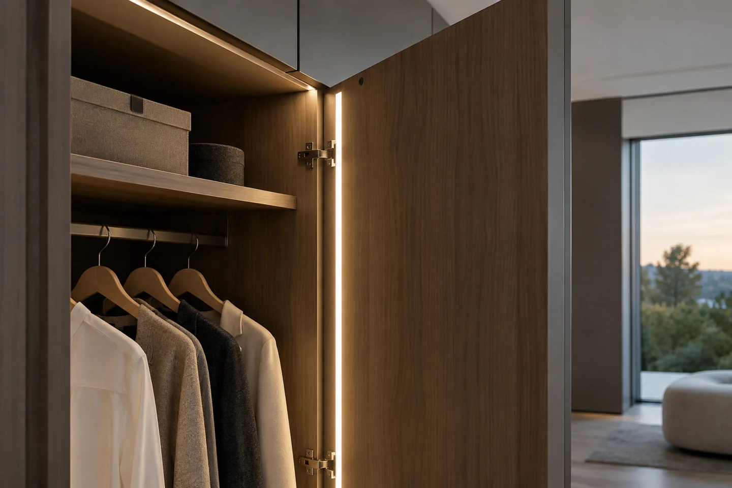
Define the switching logic before wiring the range. Door movement and body detection require different sensing layouts.
View the solution →
Assess clothes, shoes and bag materials under the intended viewing conditions, with the chosen driver and control.
View the solution →Use a compartment schedule to distinguish hanging rods, vertical light lines and illuminated shelves. Door movement, stored clothing and internal fittings affect both sensor coverage and cable clearance. Record the switching zones before repeating the kit across a range.
DESIGN DECISIONS
A wardrobe & walk-in closet systems brief should distinguish the visible effect from the assembly needed to achieve it. Start with the furniture sections and the way the space is used. Each detail below addresses its own installation, control and maintenance decisions; it should not inherit a specification simply because it sits in the same room.
| Decision | Required input | Review with the sample |
|---|---|---|
| Illuminated Closet Hanging Rods | Specify rail lengths, support positions and the mechanical load basis. Show the panel cable exit and the fittings that remain removable for service. | Review the rail with representative garments and the agreed support arrangement. Check source visibility, diffuser retention and lead relief, then retain the approved mechanical and optical details. |
| PIR Motion & Door Touch Sensor Kits | Identify door types, compartments and approach paths. Define whether one door controls its own compartment or all lights, and mark potential sensor obstructions. | Test approach, occupancy and door movement on a representative wardrobe. Check the usable light period and switch-off behaviour, then keep the validated sensor position with the drawing. |
| Tunable White CCT Shelving | List the displayed materials, required white-light range and control positions. Separate any R9 requirement from general CRI and CCT values in the brief. | Compare garments and finishes at the intended settings and dimming levels. Request the relevant model and CCT colour-rendering data and retain the approved control settings. |
Use the scene images above with the corresponding installation notes below. A lighting detail should not inherit an unrelated wiring or mounting arrangement.
Specify rail lengths, support positions and the mechanical load basis. Show the panel cable exit and the fittings that remain removable for service.
Review this detail →Identify door types, compartments and approach paths. Define whether one door controls its own compartment or all lights, and mark potential sensor obstructions.
Review this detail →List the displayed materials, required white-light range and control positions. Separate any R9 requirement from general CRI and CCT values in the brief.
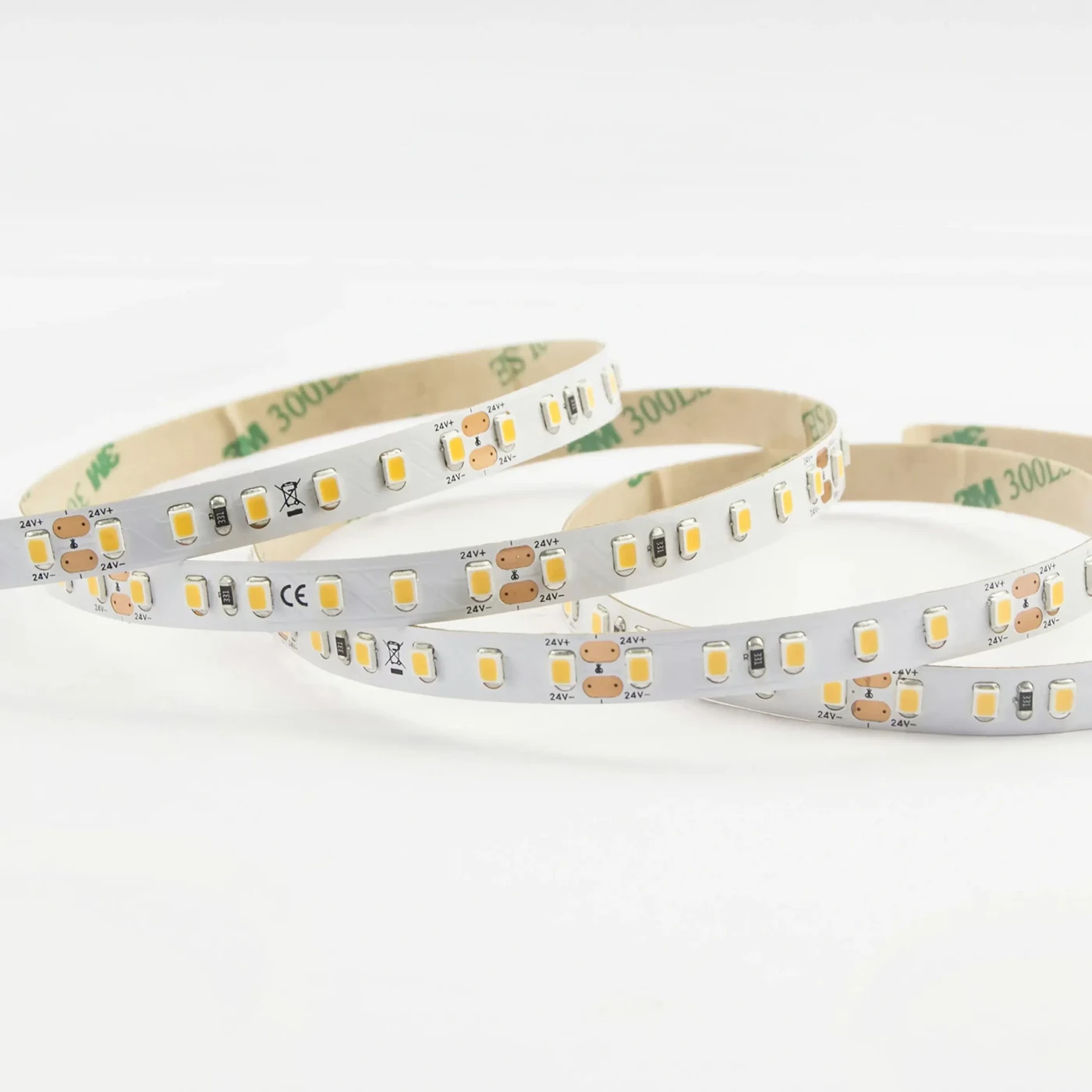
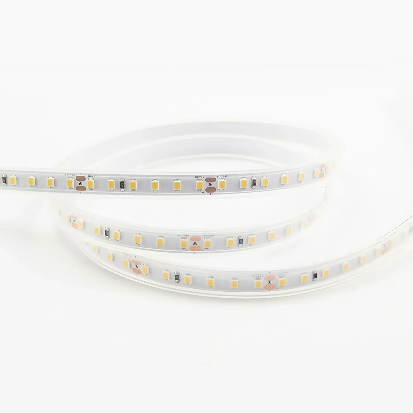
Review this detail →Photographs support the adjacent selection decisions. The exact delivered components and their performance need their own drawings, documents and sample review.
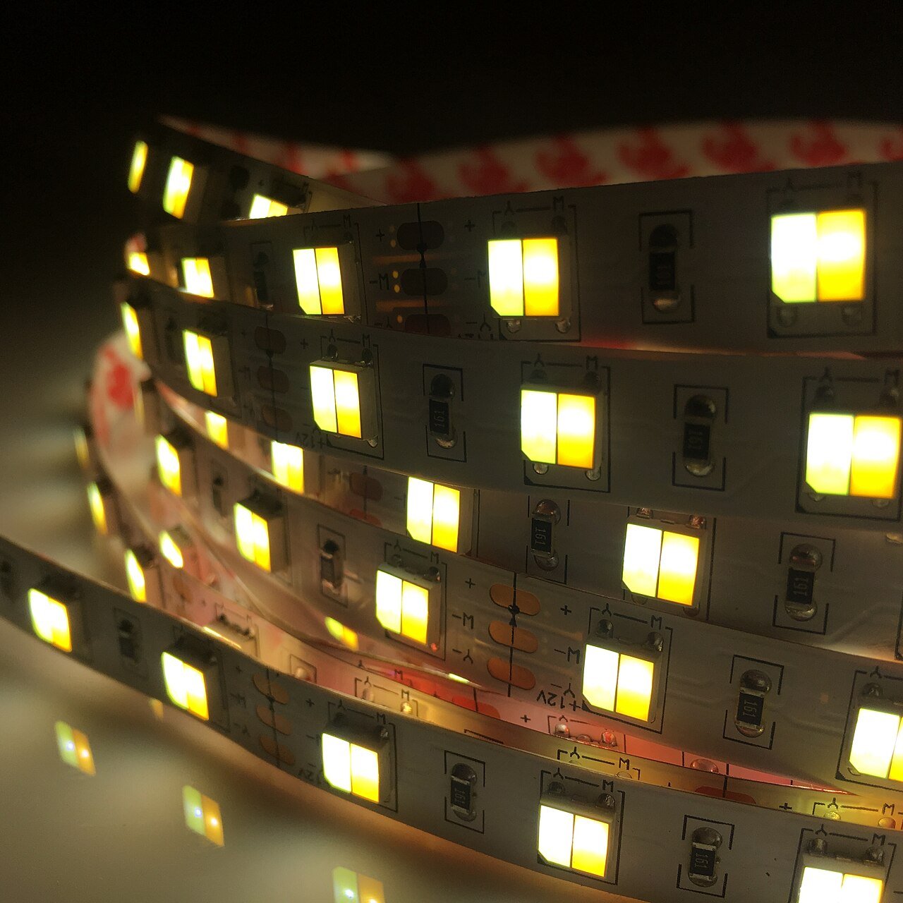
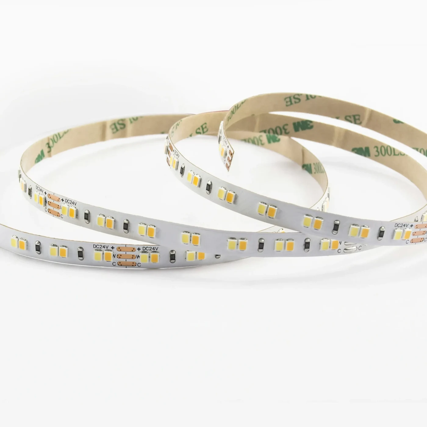
The photograph shows the physical arrangement of a tunable-white strip. Colour appearance in a photograph is not a CCT or colour-rendering measurement.
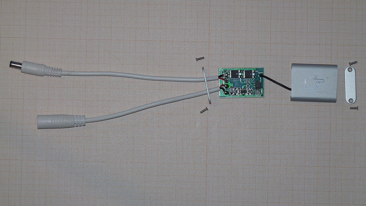
The reference shows a touch dimmer and its enclosure. Keep the electronics, mounting and cable clearances in the component schedule; it is not a PIR sensor.
Use these selection questions in the assembly brief. Confirm availability, compatibility and performance for the proposed configuration.
Confirm rail support, load requirement, diffuser retention and cable exit.
Specify each finished length, end treatment and section label.
Show how the lead passes through the panel and remains accessible.
Confirm the detection zone, timeout and behaviour through the installed diffuser or sensor opening.
Record actuator positions and the logic for multiple doors.
Check fixing access and visibility at the panel edge.
Coordinate the groove with panel thickness, hardware and corner clearances.
Identify connector pairs, lead lengths, labels and the routing sequence.
Confirm channel allocation and the useful adjustment range on the actual controller.
Specify the required R9 and request the matching spectral report; CRI alone is not an R9 value.
Compare the source with the fixture dimensions and intended light effect. A complete supply schedule also identifies the profile, controls, connectors and the work included in the assembly.
State the quantity basis and open decisions. A labelled assembly schedule keeps design, purchasing and installation working from the same reference.
FREQUENTLY ASKED QUESTIONS
Practical answers for the furniture drawing, sample review and purchasing brief.
Ask a project question →Do not infer the mechanical rating from the light output or diameter. Confirm the rod, supports, span and fastening arrangement separately from the electrical specification. Test the proposed furniture assembly against the agreed mechanical requirements.
A door sensor can follow a defined door-open state. PIR operation depends on detection position and movement, and may time out while someone remains still. Choose against the intended use and demonstrate the selected behaviour in the actual cabinet layout.
It allows the white appearance to be adjusted within the selected system’s range. Confirm the strip channels, controller and user settings together. Review fabrics at the intended settings; colour temperature alone does not establish faithful colour rendering.
Plan vertical routes, shelf feed exits and removable access points on the joinery drawings. Keep joints out of load-bearing rod supports and door hardware. Identify which modules can be removed without dismantling adjacent panels.
CONTINUE THE SPECIFICATION
Use the wider furniture brief to coordinate this lighting detail with adjacent modules and project teams.
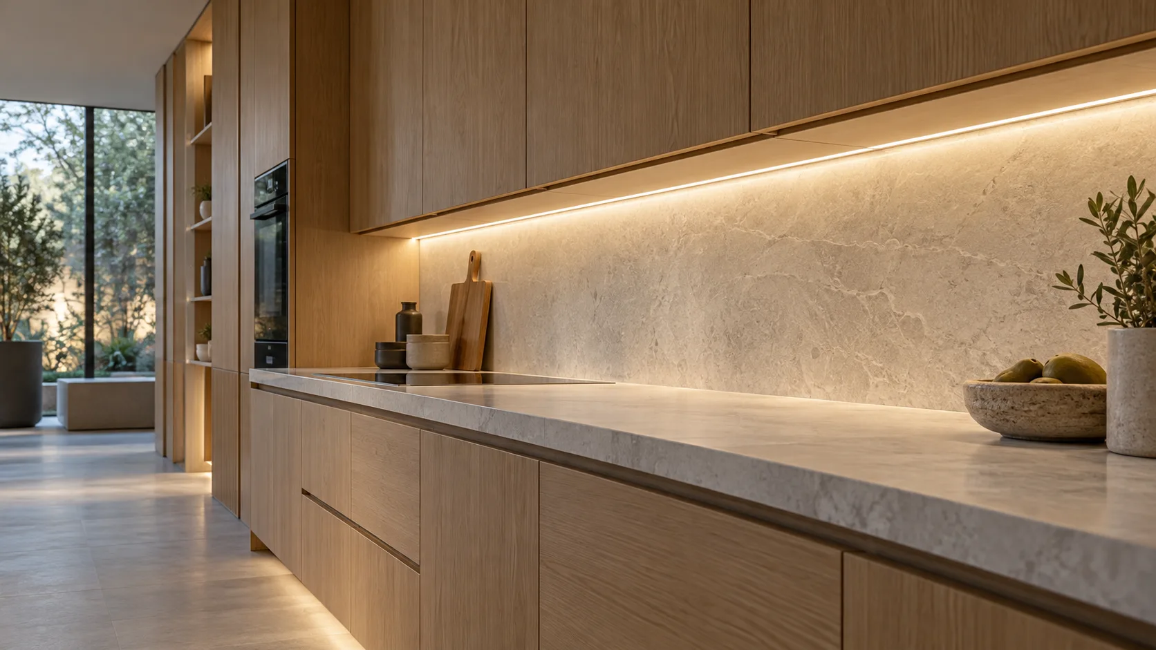
Worktop light, concealed cable routes and coordinated sensors—planned as one cabinet assembly, with cut lengths and connectors identified for each module.
View the solution →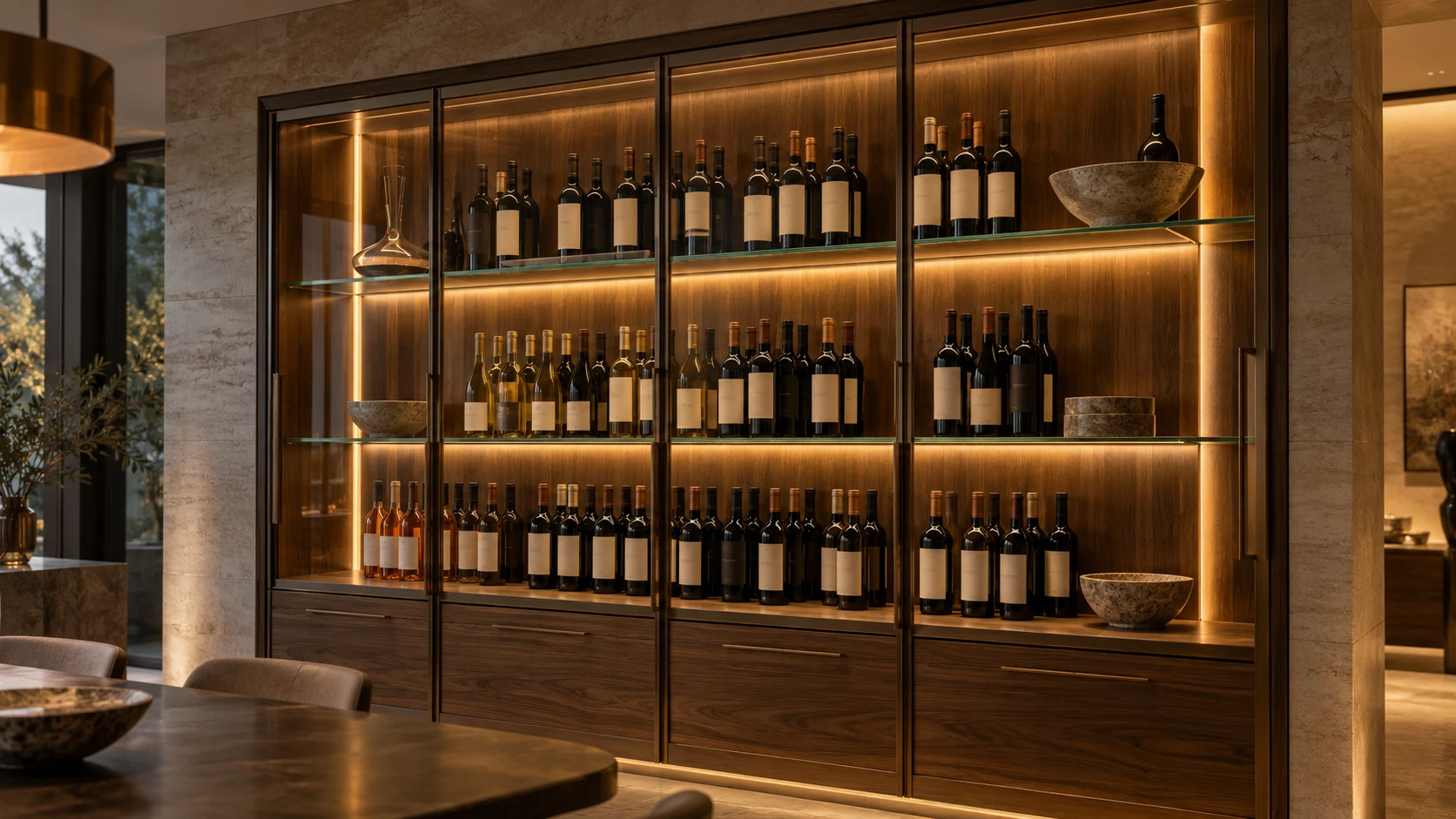
Quiet, warm light for bottle displays and glazed cabinets. Resolve shelf edges, reflections, cable visibility and thermal conditions before approving the assembly.
View the solution →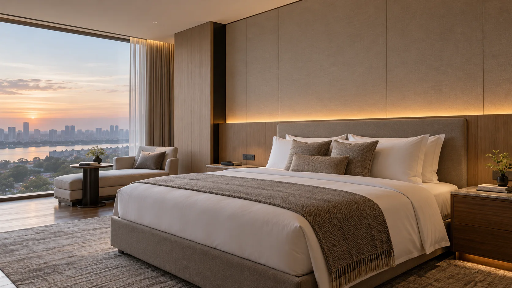
Repeatable lighting modules for shelves, headboards and fitted furniture. Keep the cut schedule, connectors, driver locations and packing list tied to the joinery drawings.
View the solution →