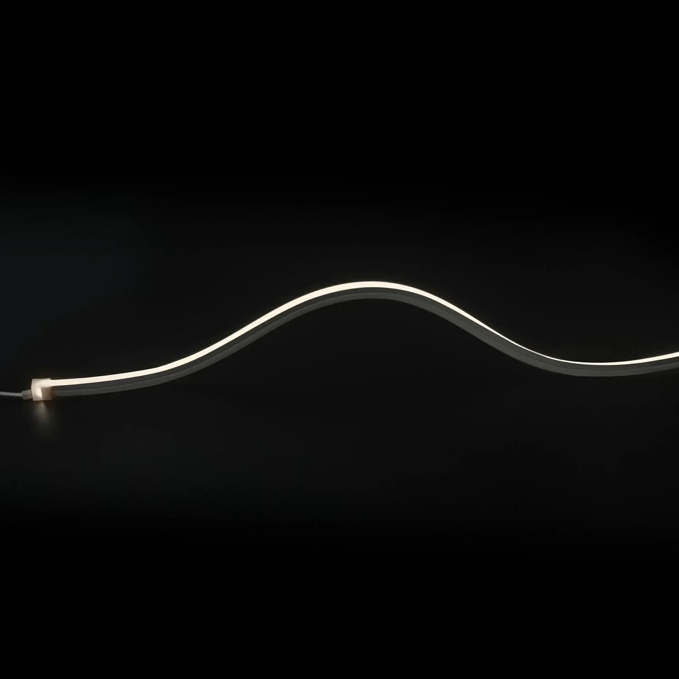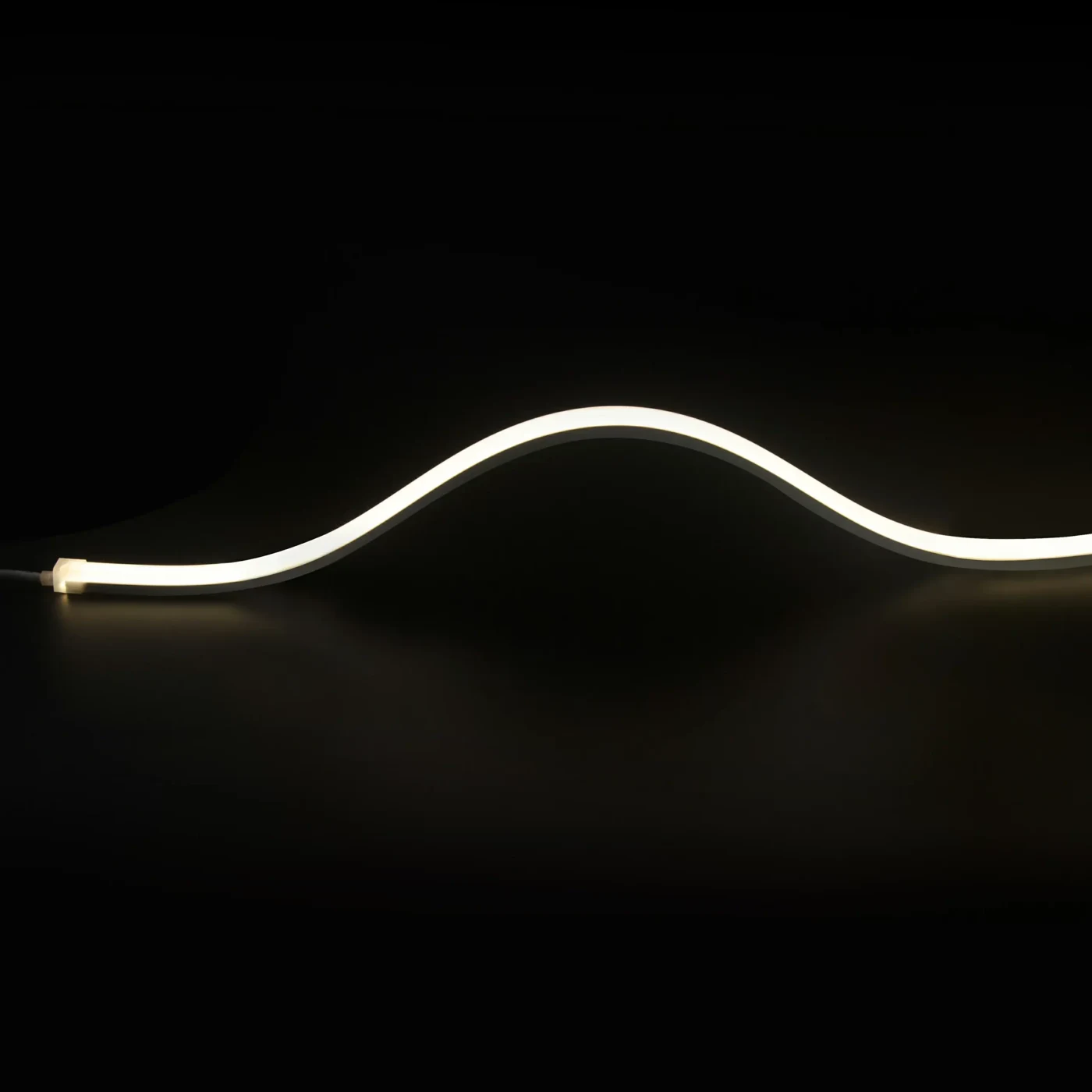
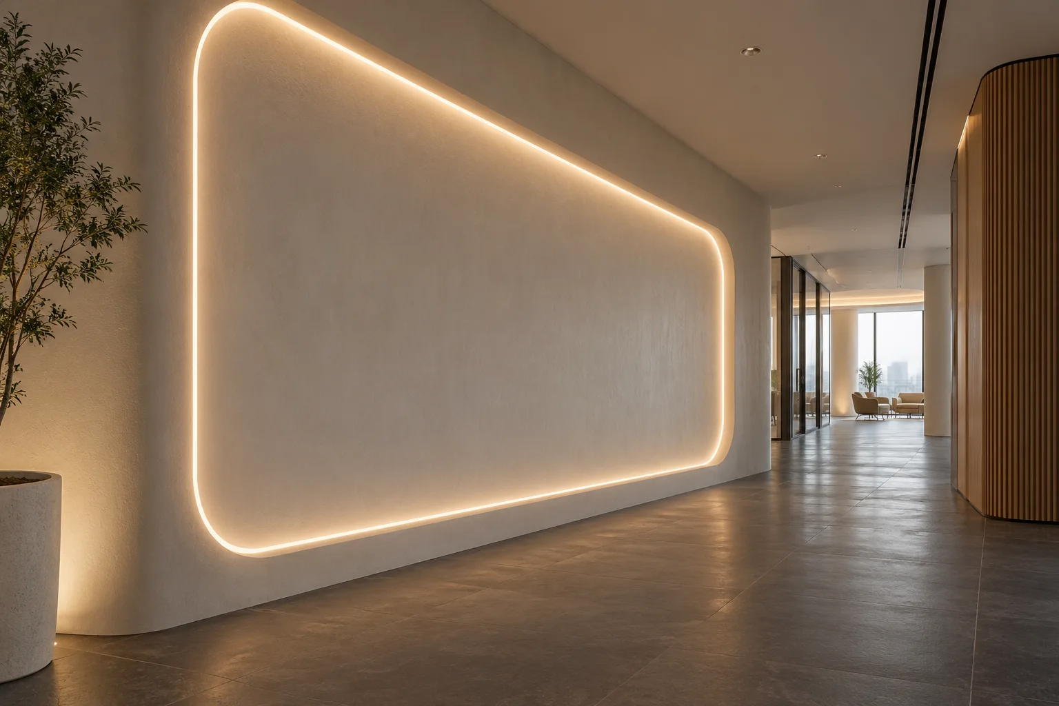
Plaster-In Trimless Gypsum Profiles
Resolve the profile-to-board detail, joint treatment and finished light opening before the finishing trades start.
View the solution →
Linear lighting integrated with gypsum, skirting and stair details. Coordinate finish levels, cable routes, control sequences and maintenance access before closing the construction.
Discuss this assemblyLinear lighting integrated with gypsum, skirting and stair details. Coordinate finish levels, cable routes, control sequences and maintenance access before closing the construction.
Resolve the profile-to-board detail, joint treatment and finished light opening before the finishing trades start.
View the solution →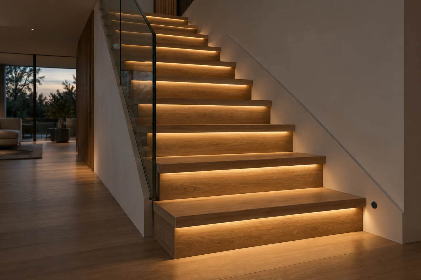
Define activation from both ends, the number of steps and the required fallback behaviour before selecting controls.
View the solution →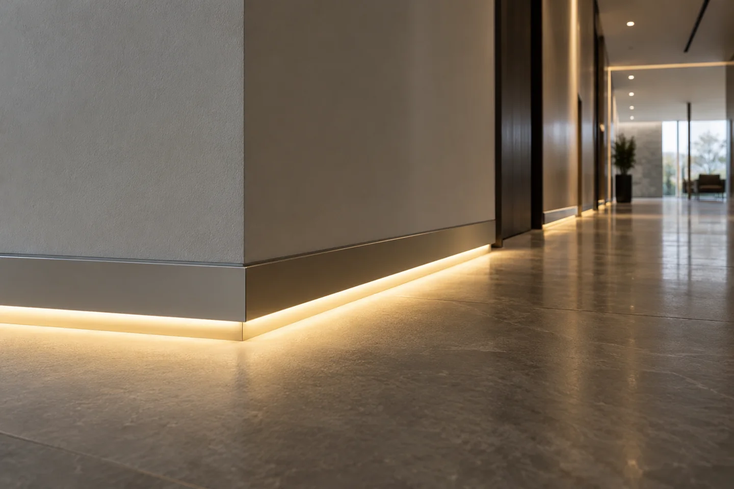
Plan a continuous line through doors, corners and finishes with identified feed points and replaceable light sections.
View the solution →Coordinate the profile with the wall or floor build-up before finishing. Separate trimless lines, skirting and sequential stair controls into distinct assemblies. Mark feed points, corners, controller access and the parts that must remain replaceable.
DESIGN DECISIONS
A trimless details & stair lighting brief should distinguish the visible effect from the assembly needed to achieve it. Start with the furniture sections and the way the space is used. Each detail below addresses its own installation, control and maintenance decisions; it should not inherit a specification simply because it sits in the same room.
| Decision | Required input | Review with the sample |
|---|---|---|
| Plaster-In Trimless Gypsum Profiles | Show board layers, profile flange, finished reveal and junctions. Coordinate the section revision before closing the construction and mark the light-section replacement route. | Inspect a finished mock-up for straightness, source shielding and service access. Retain the approved section and finishing detail so the light opening is reproducible. |
| Cascade Motion Sensor Stair Lighting | Provide step count, section lengths, top and bottom sensing positions and the intended sequence. Agree simultaneous approach, timeout and any steady-light or fallback behaviour. | Trial approach from both ends and the expected walking conditions. Check every channel and fallback mode and retain settings with the step-to-channel schedule. |
| LED Skirting Board Baseboard Systems | Draw runs, doors, corners and the floor junction. Define light direction, cleaning exposure and accessible feeds before ordering the profile lengths. | Inspect the actual floor and wall finishes, including corners and breaks. Check continuity, source images and service access, retaining the joint and feed schedule with the approval. |
Use the scene images above with the corresponding installation notes below. A lighting detail should not inherit an unrelated wiring or mounting arrangement.
Show board layers, profile flange, finished reveal and junctions. Coordinate the section revision before closing the construction and mark the light-section replacement route.
Review this detail →Provide step count, section lengths, top and bottom sensing positions and the intended sequence. Agree simultaneous approach, timeout and any steady-light or fallback behaviour.
Review this detail →Draw runs, doors, corners and the floor junction. Define light direction, cleaning exposure and accessible feeds before ordering the profile lengths.
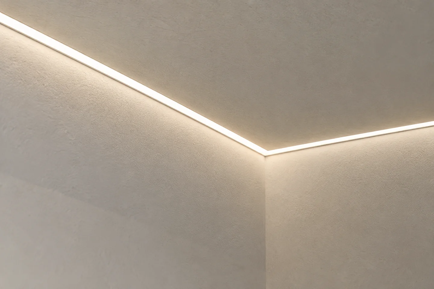
Review this detail →Photographs support the adjacent selection decisions. The exact delivered components and their performance need their own drawings, documents and sample review.
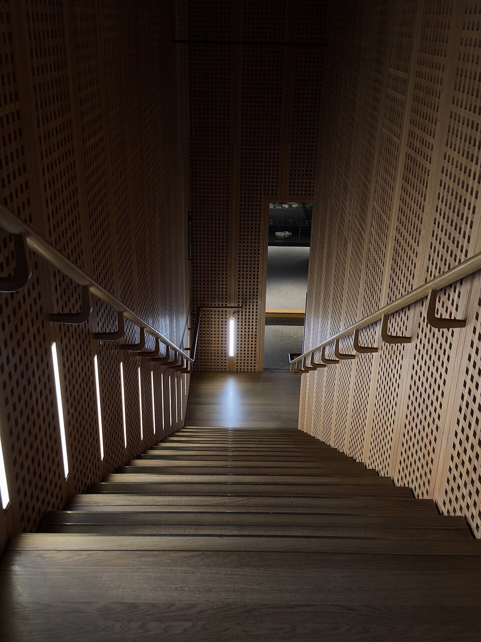
This real reference shows stair-side linear wall lighting. It illustrates architectural integration and viewing conditions, not sequential step control or a measured safety-lighting design.
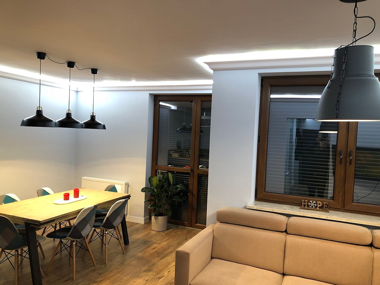
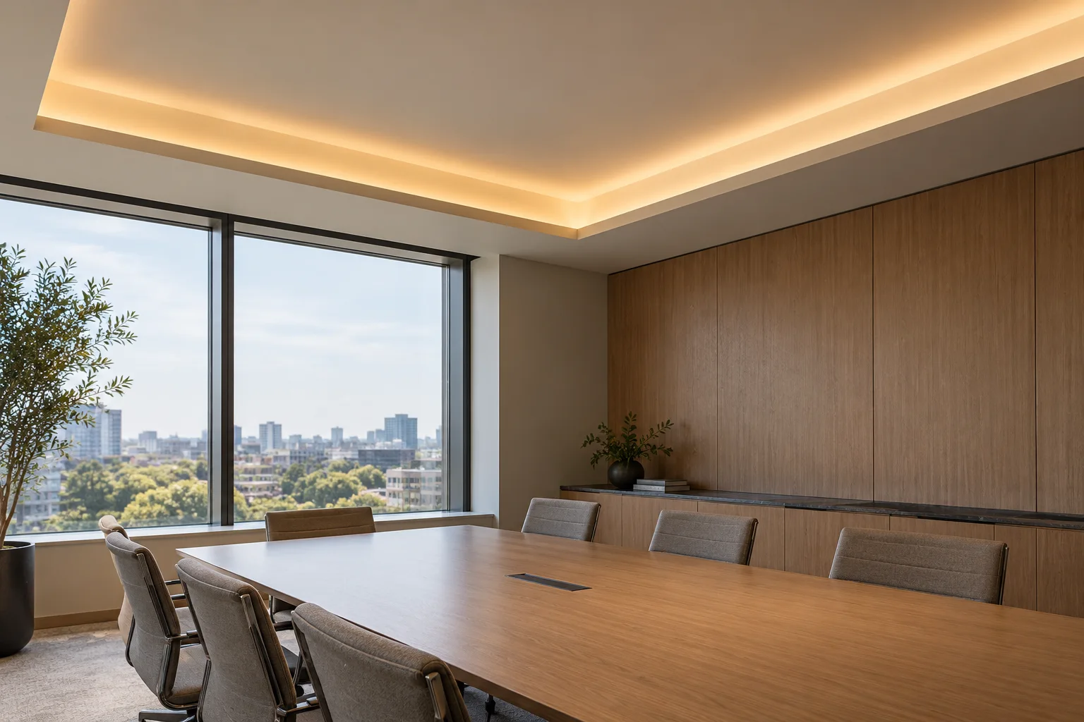
The photograph is an external cove-lighting reference. It does not establish the profile section, source model or measured colour temperature of another installation.
Use these selection questions in the assembly brief. Confirm availability, compatibility and performance for the proposed configuration.
Check the board build-up, fixing and diffuser access.
Coordinate internal or external corners with the actual section drawing.
Review source shielding and the final reveal.
Agree how the edge is finished and how the light assembly can be serviced.
Confirm detection coverage, step allocation and the installation environment.
Record timing, direction, channel loads and the desired steady-light mode.
Confirm addressing, signal wiring and channel compatibility; DMX512 alone does not establish a safety-lighting function.
Check the floor junction, corner accessories and cable access.
Review the intended setback, wall finish and optical data rather than assuming a uniform wash.
Compare the source with the fixture dimensions and intended light effect. A complete supply schedule also identifies the profile, controls, connectors and the work included in the assembly.
State the quantity basis and open decisions. A labelled assembly schedule keeps design, purchasing and installation working from the same reference.
FREQUENTLY ASKED QUESTIONS
Practical answers for the furniture drawing, sample review and purchasing brief.
Ask a project question →Before boarding and finishing details are fixed. Confirm the profile section, fixing points, joint treatment and cable route with the trades involved. Identify how the light section and diffuser will be replaced after the surrounding surface is finished.
Provide the step count, channel lengths, cable paths, sensor positions and the required sequence. Define retriggering, a paused user and simultaneous approaches from both ends. Confirm the selected controller can deliver that behaviour.
Do not assume it can. Keep the decorative sequence and the required safety or emergency lighting design separate in the project brief. The responsible project team should define the applicable provisions and operating conditions.
List internal corners, external corners, doorway returns and run terminations. Coordinate the extrusion joint with the electrical connection and floor tolerance. A mechanical corner piece does not automatically continue the light source or circuit.
CONTINUE THE SPECIFICATION
Use the wider furniture brief to coordinate this lighting detail with adjacent modules and project teams.
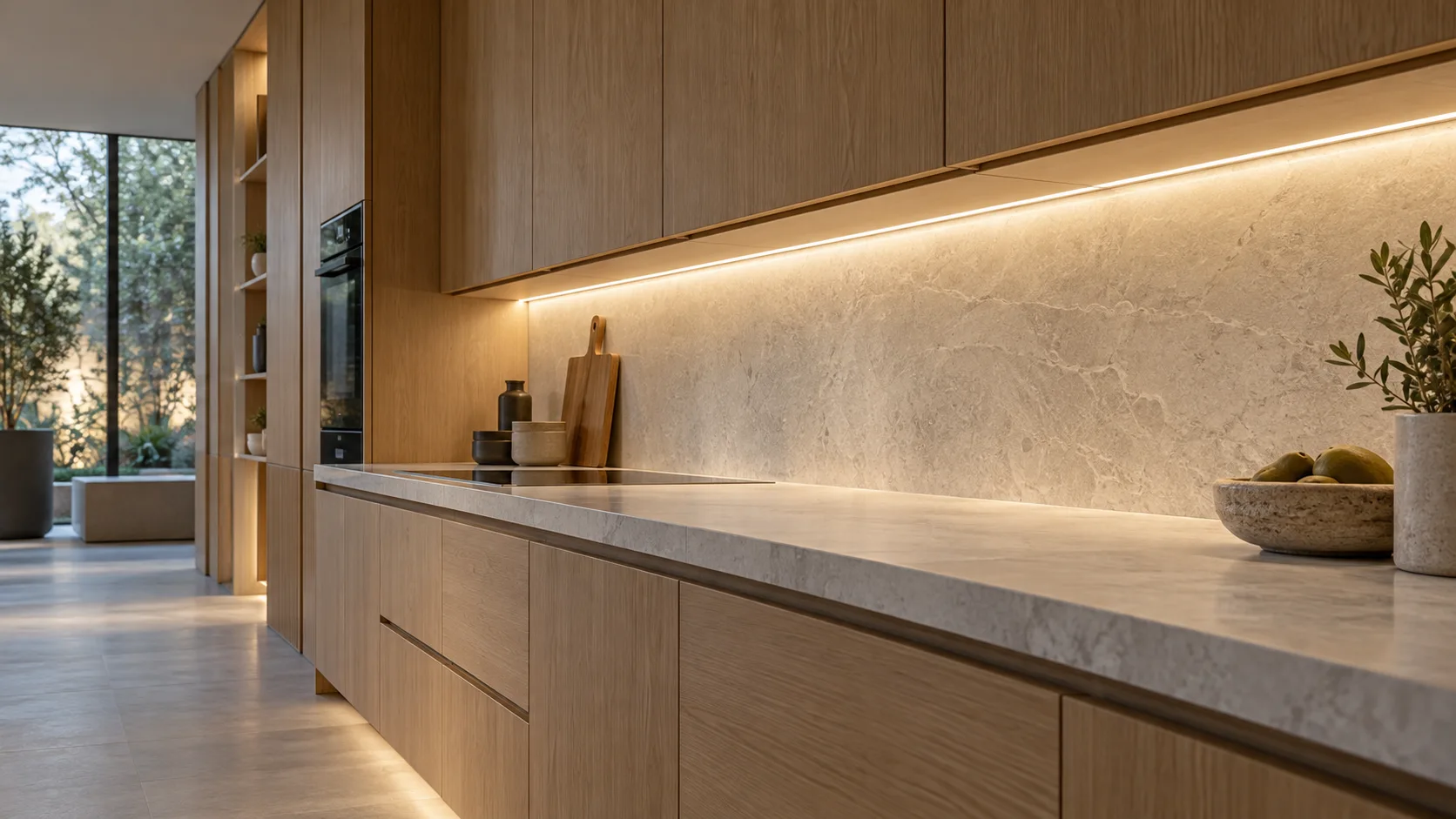
Worktop light, concealed cable routes and coordinated sensors—planned as one cabinet assembly, with cut lengths and connectors identified for each module.
View the solution →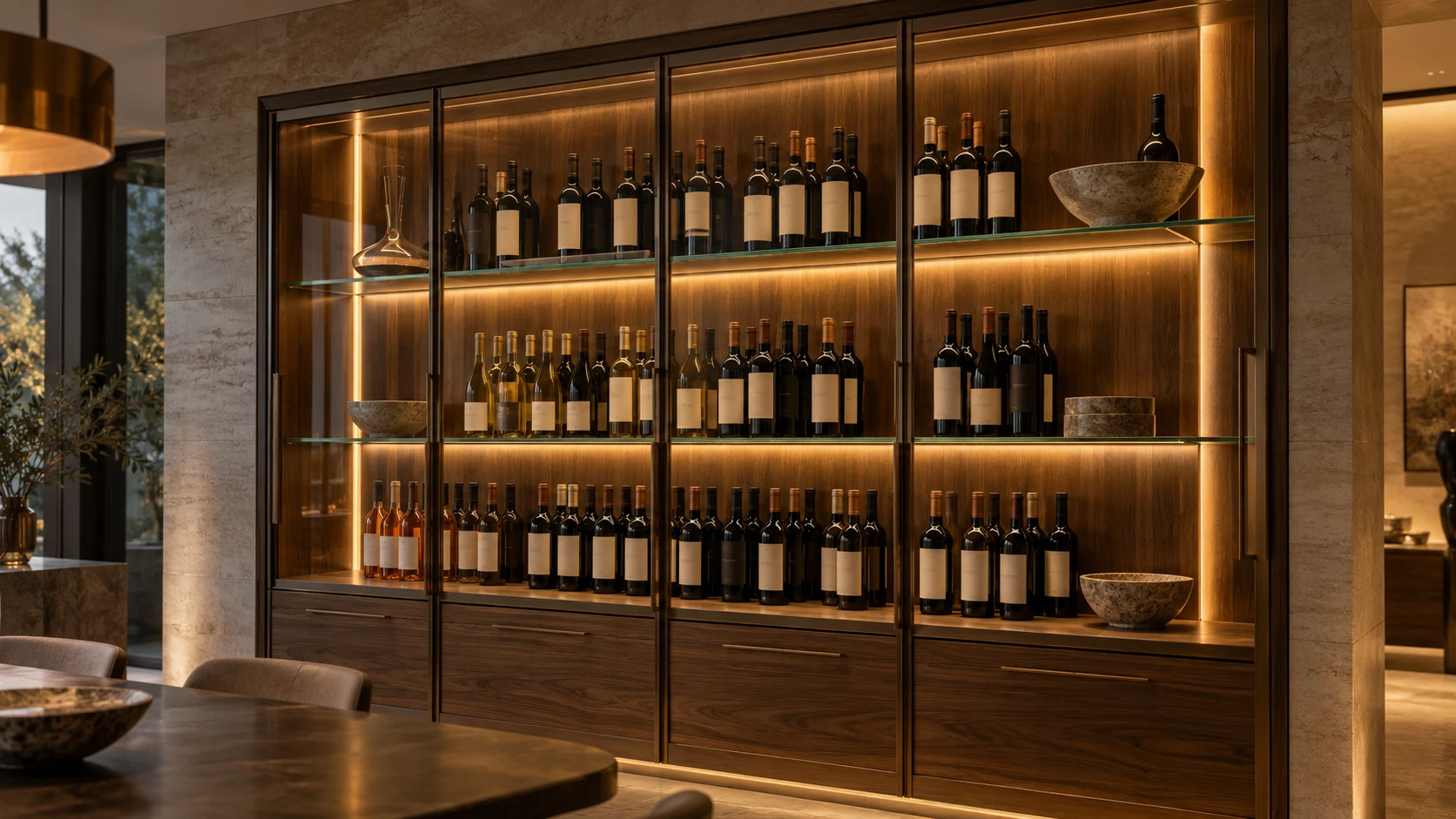
Quiet, warm light for bottle displays and glazed cabinets. Resolve shelf edges, reflections, cable visibility and thermal conditions before approving the assembly.
View the solution →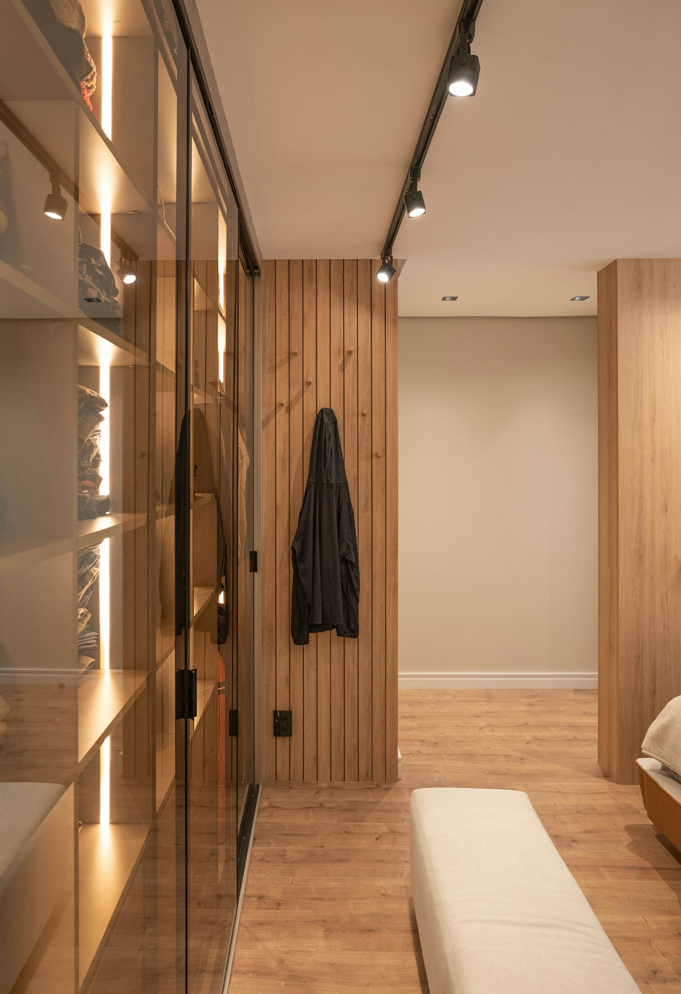
Integrated light for hanging rails, vertical panels and shoe or bag shelves. Match sensing, cable routes and light colour to each compartment.
View the solution →