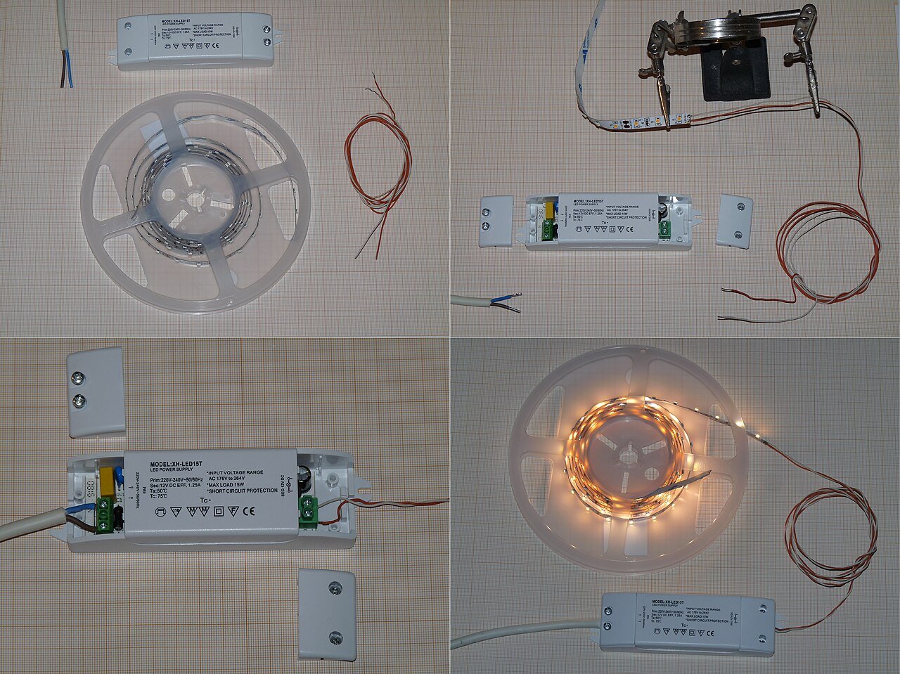
Cable exits and replaceable connections
Identify the cable exit, termination space and route back to the supply. Keep each joint reachable for inspection and replacement, and use the selected connector drawing to check the mating parts.

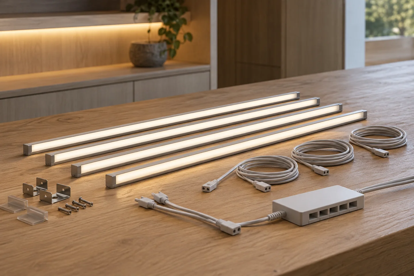
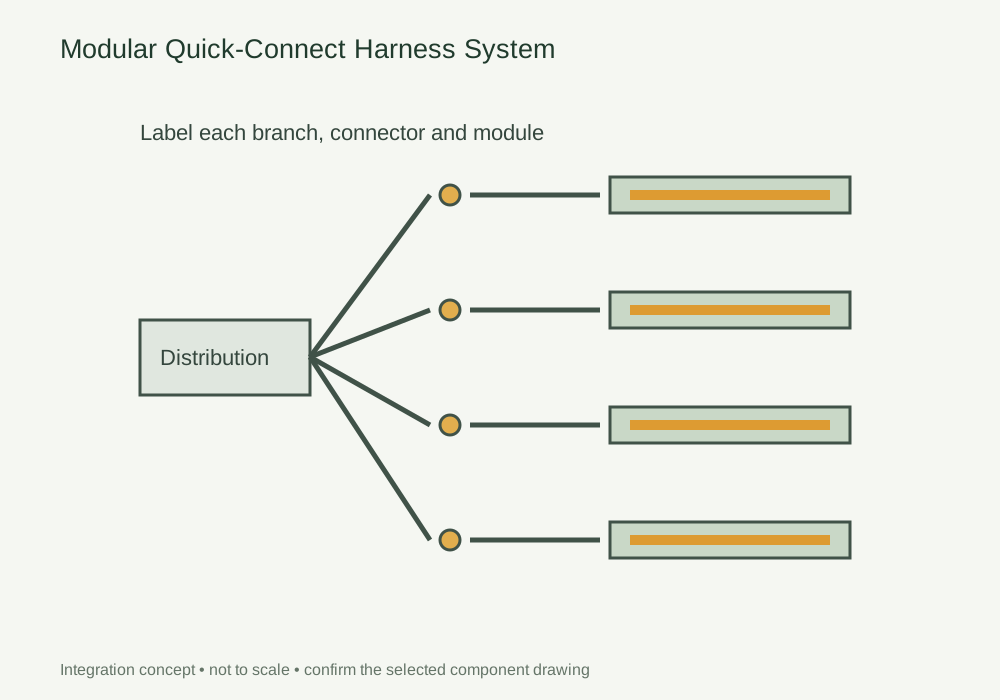
Use an assembly schedule to link each section to the correct harness branch and package.
Discuss this assemblyUse an assembly schedule to link each section to the correct harness branch and package.
Create a module schedule for light sections, sensors, drivers and leads. Include connector references, pin assignments, lengths and labels, and distinguish preassembled parts from site operations.
Check mating series, conductor size, polarity and branch loading. Physical fit alone does not establish electrical compatibility; give each assembly a traceable packing reference.
Trial the kit in its intended assembly sequence. Check labels, strain-free connections and control operation, then resolve open interfaces before authorising repeated kitting.
DESIGN DECISIONS
Quick-connect wiring reduces site operations only when the kit is complete and the mating interfaces are agreed. A connector that physically fits is not necessarily electrically compatible. Define strip sections, driver outputs, sensor inputs and branch leads in one schedule, then assign each packed assembly a reference that follows the furniture module.
| Decision | Required input | Review with the sample |
|---|---|---|
| Connector system | Series, pin count and polarity | Confirm documented mating parts rather than appearance |
| Branch design | Cable length, conductor and load | Review the most demanding branch before repetition |
| Packing | Module quantities and assembly sequence | Label the kit so the installer can identify each connection |
Use this concept to mark mounting positions, cable paths and service clearances on your fixture drawing. Dimensions and component references belong on the project drawing before machining.
Photographs support the adjacent selection decisions. The exact delivered components and their performance need their own drawings, documents and sample review.
Identify the cable exit, termination space and route back to the supply. Keep each joint reachable for inspection and replacement, and use the selected connector drawing to check the mating parts.
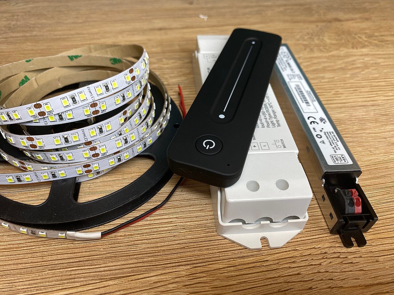
The photograph shows a strip, controller and supply together. Confirm the selected assembly’s voltage, load, control interface and service envelope; this is not a PIR or cascade controller specification.
Use these selection questions in the assembly brief. Confirm availability, compatibility and performance for the proposed configuration.
List finished length, lead orientation and identification for every module.
Confirm branch current, polarity and connector mating before assembly.
Define which connections are preassembled and which remain site operations.
Compare the source with the fixture dimensions and intended light effect. A complete supply schedule also identifies the profile, controls, connectors and the work included in the assembly.
This detail includes components beyond an LED strip. The catalogue does not identify a complete, approved kit for this arrangement. Send the fixture section and required operation so the source, control and mechanical interfaces can be reviewed together.
Compare catalogue light sources → Review the wider furniture system →
Discuss components for this detailState the quantity basis and open decisions. A labelled assembly schedule keeps design, purchasing and installation working from the same reference.
FREQUENTLY ASKED QUESTIONS
Practical answers for the furniture drawing, sample review and purchasing brief.
Ask a project question →Do not infer interchangeability from a similar size or a generic description. Confirm the exact mating series, pin assignment and electrical rating.
A bill of materials, module quantities, finished lengths, connector references, branch labels, packing arrangement and the operations remaining for the installer.
Compare the mating series, pin allocation, polarity, wire size and permitted load in the component documents. Label approved harness variants. Connector appearance alone is insufficient for substitution.
Include Drawing revision and finished dimensions, Module quantity and order basis, Source, profile and control references. Add quantities by furniture module and identify the configuration or sample already selected. This gives the drawing review a defined scope before pricing and assembly approval.
CONTINUE THE SPECIFICATION
Use the wider furniture brief to coordinate this lighting detail with adjacent modules and project teams.

Coordinate machining, light direction and the shelf support before the section is released for cutting.
View the solution →
Plan the ambient effect around seated and sleeping eye positions, with switches and service points within reach.
View the solution →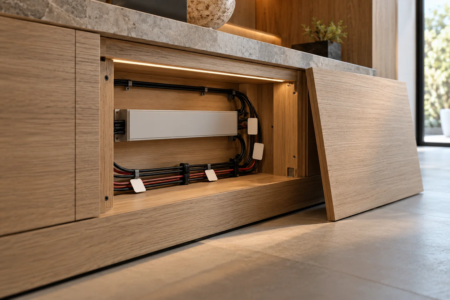
Added as the twentieth subscene: reserve an accessible electrical compartment and a route for replacement without dismantling finished joinery.
View the solution →