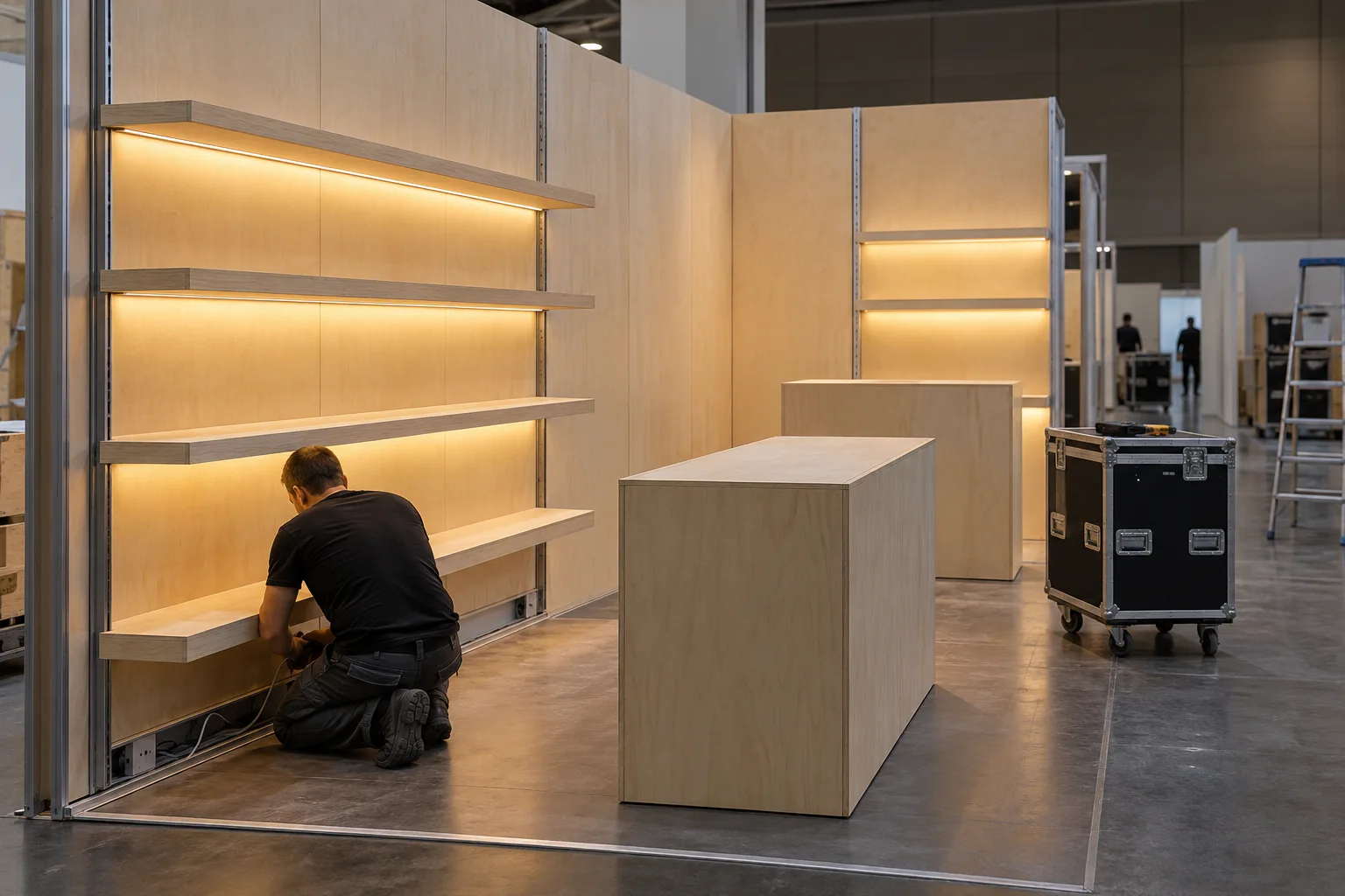
AI-generated concept illustration for module and service-access discussions; not a completed exhibition project.
Order lighting around the modules your team will assemble again
Exhibition contractors and stand-system manufacturers need a lighting package that fits more than the first event layout. Repeated walls, shelves and counters may be arranged differently at the next venue, while the assembly team needs clear connections and identifiable replacement parts. When sourcing modular exhibition lighting kits, define the reusable module and distinguish it from the layout-specific wiring. That gives suppliers a basis for quoting complete kits, spare assemblies and optional configurations. It also lets the stand builder review what can be prepared in the workshop and what must be connected during each installation.
Display walls and illuminated frames
Identify which wall and frame elements can be interchanged and which have an orientation-specific light detail. Map connections to the stand system’s assembly points, including corners and end panels. Keep concealed cable routes within the defined module envelope so changing a wall arrangement does not require cutting new passages during event installation.
Product shelves and presentation counters
For trade show shelf lighting, evaluate shelf and counter modules with the objects the stand is intended to display. Include adjustable shelves and staff-side access in the review, because these affect both lighting and setup work. Define the connection associated with each module so its identity remains clear when several similar parts are unpacked together.
Brand contours and decorative features
A repeated brand feature may need a different source assembly from the product displays around it. Show how that feature separates for transport and returns to its intended shape at setup. Keep visible-source mounting and any flexible-section handling requirements with the packing and assembly drawings rather than assuming installers will infer them from the finished appearance.
See the installation behind the specification.
Each view addresses a named lighting detail. Illustrations show the design intent; select the actual components against the drawing and a representative sample.
AI-generated application illustration; not a completed BEXLIGHT project or measured performance. Component interfaces are illustrative.
Under-Shelf Recessed Joinery Lighting
Coordinate machining, light direction and the shelf support before the section is released for cutting.
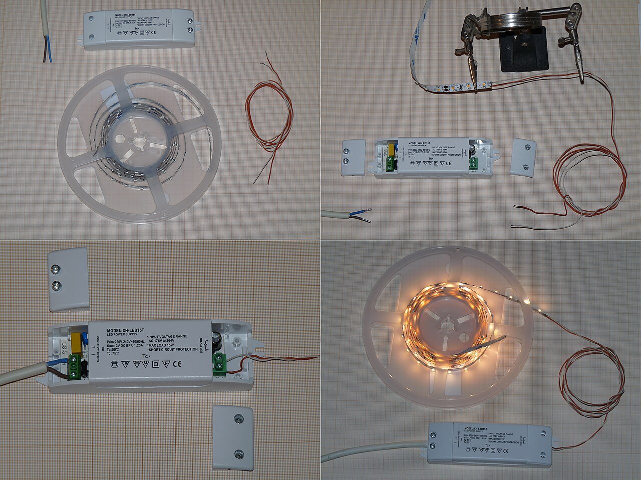
Photographs support the adjacent selection decisions. The exact delivered components and their performance need their own drawings, documents and sample review.
External reference photograph. Not a BEXLIGHT installation or a supplied component approval. Reproduced unchanged. Photo: Dmitry G · License.
Cable exits and replaceable connections
Identify the cable exit, termination space and route back to the supply. Keep each joint reachable for inspection and replacement, and use the selected connector drawing to check the mating parts.
A source that fits the finished detail.
Compare the light line, assembly envelope and control requirements together. The routes below are starting points for a specification discussion.
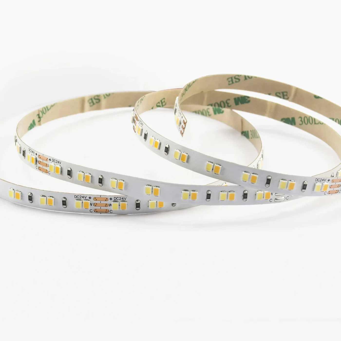
Catalogue reference SR005-140P2835IP20TW; final configuration requires review.
For defined shelf and frame modules inside the stand system
Consider SMD strip assemblies where profiles and covers can remain attached to reusable furniture modules. Review the complete module with its connections, merchandise and packing arrangement so source selection fits the stand contractor’s actual assembly workflow.
Repeated handling suitability depends on the whole module and connection system. Source construction alone does not establish a reusable kit’s durability.
Catalogue reference SR006-1004TF-140P2835IP67; final configuration requires review.
For visible brand lines with a controlled assembly shape
Consider Neon Flex for a visible contour whose shape and illuminated-face orientation are defined by the stand structure. Review the product’s geometry and mounting instructions alongside the disassembly, packing and reinstallation sequence before selecting finished sections.
A flexible source should not be packed by assumption. Follow exact handling instructions and evaluate the proposed supports and transport arrangement.
Use the fixture drawing, component documentation and a representative assembly to turn the visual brief into a repeatable specification.
01
Create a module map
List wall, shelf, counter and contour modules with their light sections. Give interchangeable parts a shared specification and non-interchangeable parts a clear identity. Record the actual stand layouts the kit must support. A total metre quantity alone does not reveal how the next layout will be powered or controlled.
02
Plan repeat connections
Show connector location, polarity and cable routing for the assembly team. Select and verify the connection system against the expected use and manufacturer instructions; do not assume a permanent strip connector is suitable for repeated handling. Keep strain from assembly and packing away from the source termination.
03
Make commissioning a repeatable task
Provide a labelled harness schedule, driver allocation and scene settings. Include a defined inspection before each setup and a record for damaged or replaced modules. Obtain the venue and electrical contractor’s requirements for the complete installation; component documentation alone does not settle those obligations.
04
Design the packing with the kit
Show how illuminated modules, covers, leads and mounting components are restrained in transit. Test the packing and reassembly sequence with representative modules and record what changes. Store the accepted module configuration and replacement identifiers in a handover pack so a later event can reproduce the agreed lighting.
From an initial brief to a controlled assembly.
Send the module drawings, expected layouts, assembly pattern and venue requirements. Quote the initial evaluation build separately from the reusable production kit where those scopes differ.
Decision
What to check
Record or boundary
Repeat layouts
Identified modules and driver allocations
Layout and harness schedule
Repeated handling
Permitted connections and strain management
Assembly trial
Transport
Protected light faces and restrained leads
Packing and reassembly record
Module drawings and identifiers
Supported stand layouts
Workshop and site assembly split
Packing and handling method
Venue connection requirements
FREQUENTLY ASKED QUESTIONS
Application FAQ
Selection, integration and repeat-supply questions for this application.
01How do we order one kit for several stand layouts?
List the layouts the kit must support and map the modules used in each. Separate common illuminated modules from layout-specific harnesses and equipment allocations. Ask suppliers to distinguish the reusable stand lighting harness and common modules from the additional parts needed for one event configuration.
02Which lighting parts should remain assembled during transport?
Base that decision on the module construction, packing space and component handling instructions. A source and profile may remain attached to a shelf while external leads need their own restraint. Trial the proposed packing and rebuilding sequence with representative parts, then use the result to define the delivered module and the workshop assembly scope.
03How should a kit be checked before leaving for the next event?
Use a module inventory linked to the approved layout and connection schedule. Inspect the parts and confirm operation using the specified assembly method, recording damaged or replaced items against their identities. The event installation team should receive the current configuration rather than a packing list that describes only the original kit.
04What should the enquiry say about venue electrical requirements?
For exhibition fixture lighting, include known venue and contractor requirements affecting the complete stand installation, and identify conditions still awaiting confirmation. Show the intended connection point and the party responsible for site electrical work. Suppliers can then explain their component scope while the stand contractor coordinates the final installation and event-specific acceptance process.
Share the fixture or route drawing, quantities, target market and the decisions still open. Include your company and whether you are preparing a sample, a project or repeat production.