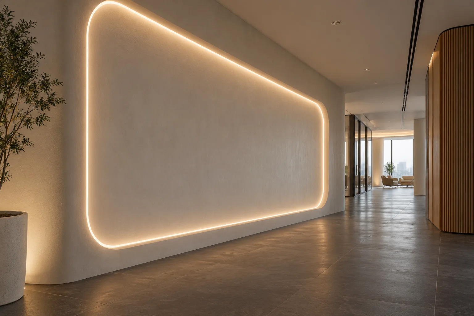
AI-generated concept illustration of a rounded architectural light contour; not a completed BEXLIGHT project, measured result or installation drawing.
Coordinate the visible line with the structure that carries it
Architectural contour projects ask a visible light source to follow a building detail that may change direction, substrate and exposure along its route. The integrator’s task is to define architectural contour lighting sections and identify the mounting and connection conditions for each. A useful enquiry therefore starts with elevations and route geometry, not a general request for outdoor neon. It should show which parts of the line are repeated, where joints can be accepted and how the installation will be reached. That information supports a source proposal the project team can meaningfully review.
Façade outlines and sheltered returns
Mark each route segment’s exposure and mounting surface rather than giving the façade one blanket description. Returns beneath canopies may present different conditions from open edges. Show structural breaks and transitions so the proposal can coordinate neon flex mounting and section boundaries with the building detail as well as the lighting route.
Interior wall and ceiling contours
An interior contour may pass through wall junctions, ceiling features and close visitor sightlines. Coordinate the luminous face with the intended view throughout those transitions. Identify where installation tolerances will be most visible and request a representative joint or curve sample that includes the intended mounting method and surrounding finish.
Curved features and changing planes
A route drawn as a smooth curve can still require the source to bend or twist in an unsupported direction. Translate the architectural line into individual segments with a consistent illuminated-face orientation. Where the route changes plane, resolve the transition as an explicit assembly detail before calculating the finished lengths for the order.
See the installation behind the specification.
Each view addresses a named lighting detail. Illustrations show the design intent; select the actual components against the drawing and a representative sample.
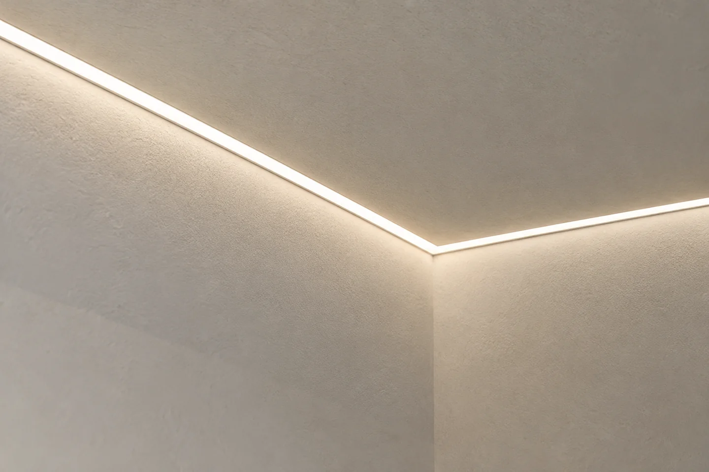
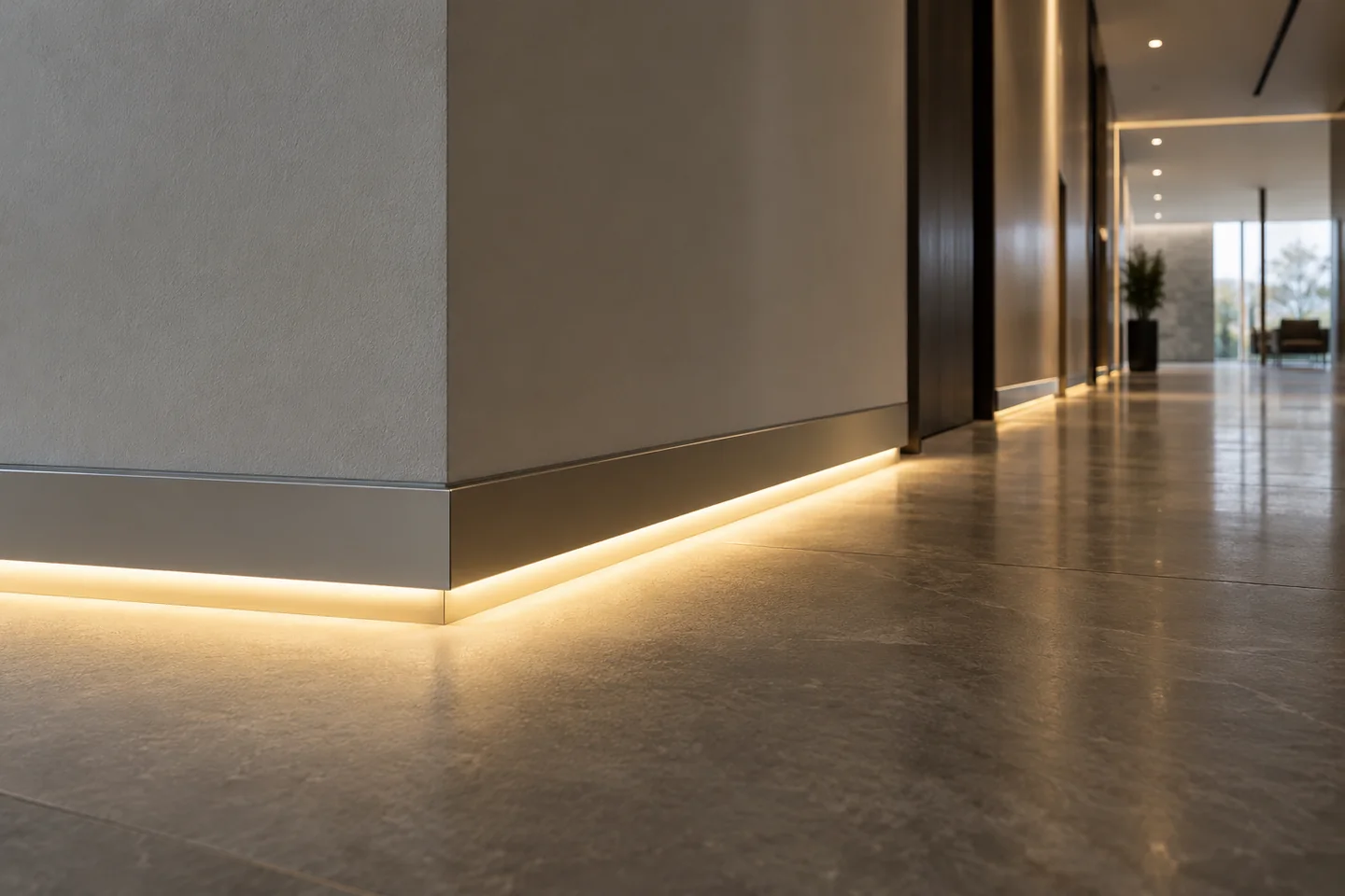
AI-generated application illustration; not a completed BEXLIGHT project or measured performance. Component interfaces are illustrative.
Plaster-In Trimless Gypsum Profiles
Resolve the profile-to-board detail, joint treatment and finished light opening before the finishing trades start.
Photographs support the adjacent selection decisions. The exact delivered components and their performance need their own drawings, documents and sample review.
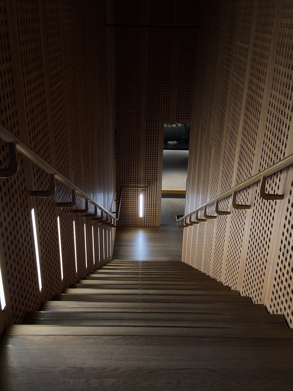
External reference photograph; not a BEXLIGHT project. Light output, CCT and component identities are not established by this photograph. Display-size reproduction. Photo: Mike is Michi · License.
Linear light along a stair route
This real reference shows stair-side linear wall lighting. It illustrates architectural integration and viewing conditions, not sequential step control or a measured safety-lighting design.
A source that fits the finished detail.
Compare the light line, assembly envelope and control requirements together. The routes below are starting points for a specification discussion.
Catalogue reference SR006-1004TF-140P2835IP67; final configuration requires review.
For a visible contour matched to documented product geometry
Consider Neon Flex where the luminous face is intended to remain visible. Select the exact product against the route’s bending plane, cross-section envelope, mounting detail and environmental brief before approving the coordinated section and termination schedule.
An outdoor description does not cover every exposure. Review exact-model and finished-assembly evidence against the project’s actual conditions and installation detail.
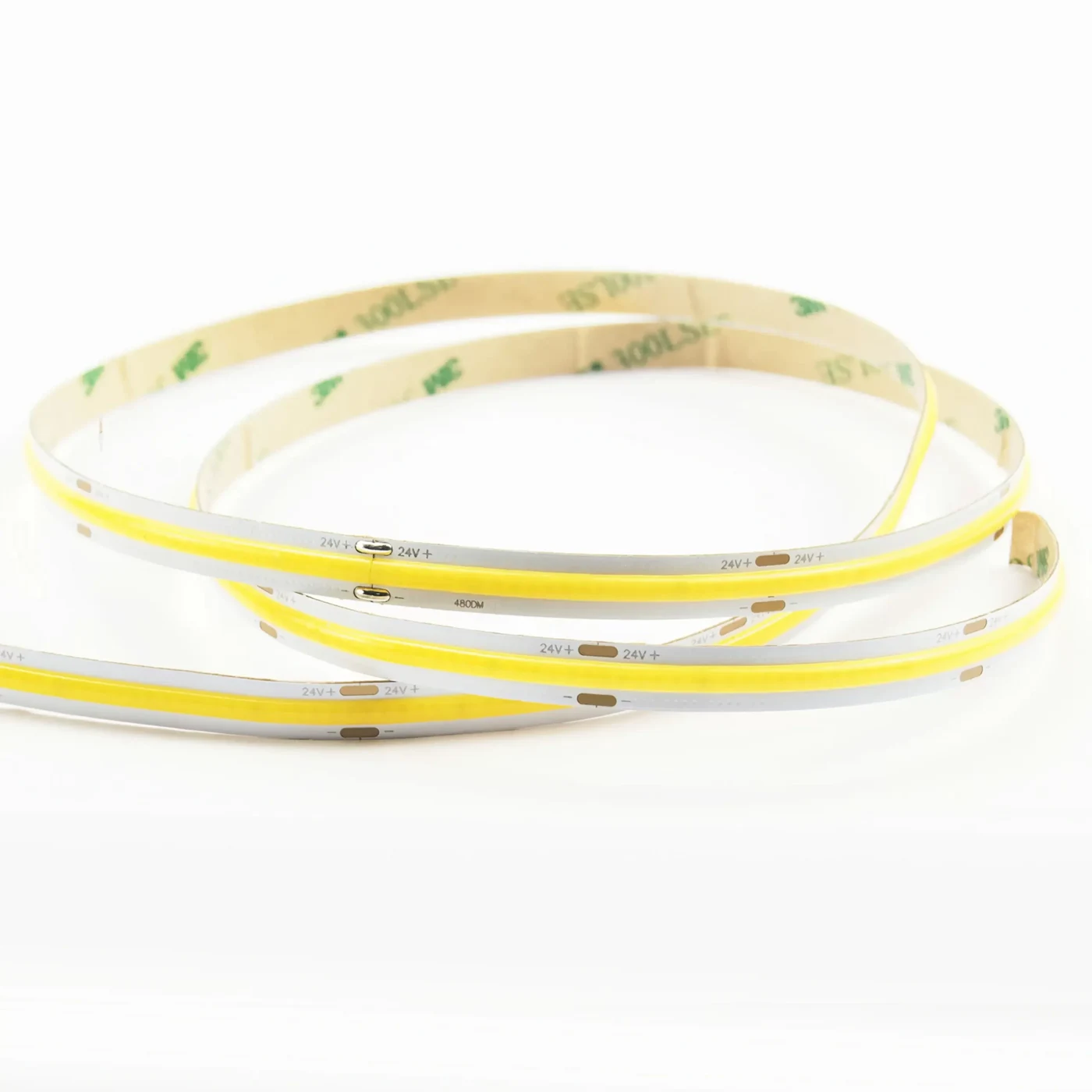
Catalogue reference SR005-320PCOBIP20; final configuration requires review.
For concealed architectural reveals alongside the contour
Consider a COB strip assembly if a particular segment is an indirect reveal rather than a visible encapsulated line. Evaluate that detail with its profile and receiving surface as a distinct assembly within the wider architectural scheme.
Do not substitute bare strip for a visible Neon Flex route on appearance alone. The mounting, optics and exposure requirements are different.
Use the fixture drawing, component documentation and a representative assembly to turn the visual brief into a repeatable specification.
01
Draw the complete route
Show straight lengths, transitions, curves, changes of plane and structural joints on an elevation. Identify the source’s lit face throughout the route. Confirm the actual permitted bending geometry from the product instructions. Split the route where a section cannot follow the proposed path without twisting or violating the allowed geometry.
02
Write the environmental brief
Describe whether the route is sheltered, rain-exposed, subject to cleaning or located near other environmental stresses. Ask for product-specific suitability and finished-assembly evidence, including the termination details. Do not infer UV, chemical, immersion or salt-exposure performance from a broad “outdoor” description.
03
Coordinate mounting and feeds
Specify the mounting method with the component manufacturer and structural/installation teams. Show feed exits and accessible equipment locations. Keep electrical section IDs aligned with visible segments so a replacement can be identified from the handover drawing. Check joints and terminations in an illuminated mock-up before approving a long repeated detail.
04
Make acceptance inspectable
Agree the viewing positions, scene and expected joint treatment. Record the assembled sample, not just a source reel. Preserve the installation instructions, configuration and as-built route schedule. This is a design-coordination method; it does not claim that any current BEXLIGHT model has been verified for every architectural exposure described here.
From an initial brief to a controlled assembly.
Provide elevations, the substrate, exposure details, route lengths and equipment access constraints. Any special environmental performance remains subject to exact-model evidence and project review.
Decision
What to check
Record or boundary
Geometry
Lit face, curves and plane changes
Product-specific route review
Environment
Actual exposure and finished terminations
Documented suitability review
Visual continuity
Joint and end treatment
Representative illuminated mock-up
Scaled elevations and route IDs
Luminous-face orientation
Substrates and mounting envelope
Segment-specific exposure brief
Joint and maintenance access locations
FREQUENTLY ASKED QUESTIONS
Application FAQ
Selection, integration and repeat-supply questions for this application.
01Can the same contour product run through interior and exterior segments?
Assess each segment against the exact product documentation and the proposed finished assembly. Interior and exterior locations may introduce different exposure, mounting and access conditions even when the design calls for one visual line. Record those differences in the building outline lighting specification so the proposal can explain shared components and any segment-specific requirements.
02Where should we place visible joints in a long architectural line?
Coordinate visible light line joints with the architectural rhythm, source section limits and maintenance access. Review the proposed end treatment under the agreed viewing conditions before accepting it as a repeated detail. A joint hidden in a drawing may remain noticeable when illuminated, so include the actual mounting and surrounding finish in the approval sample.
03What does the supplier need to review a curved route?
Provide scaled geometry, the intended luminous-face orientation and changes of plane, together with the available mounting envelope. The supplier needs enough information to compare the route with the exact product’s permitted bending instructions. Highlight uncertain transitions and construction tolerances rather than leaving them to be resolved by the installer after finished sections arrive.
04How can replacement sections be identified after project handover?
Give each physical segment a route identifier linked to its source configuration, finished length, end detail and mounting information. Retain the as-built record where maintenance teams can use it alongside access instructions. This makes a replacement enquiry specific even if several similar contour sizes or exposure conditions occur within the same building.
Share the fixture or route drawing, quantities, target market and the decisions still open. Include your company and whether you are preparing a sample, a project or repeat production.