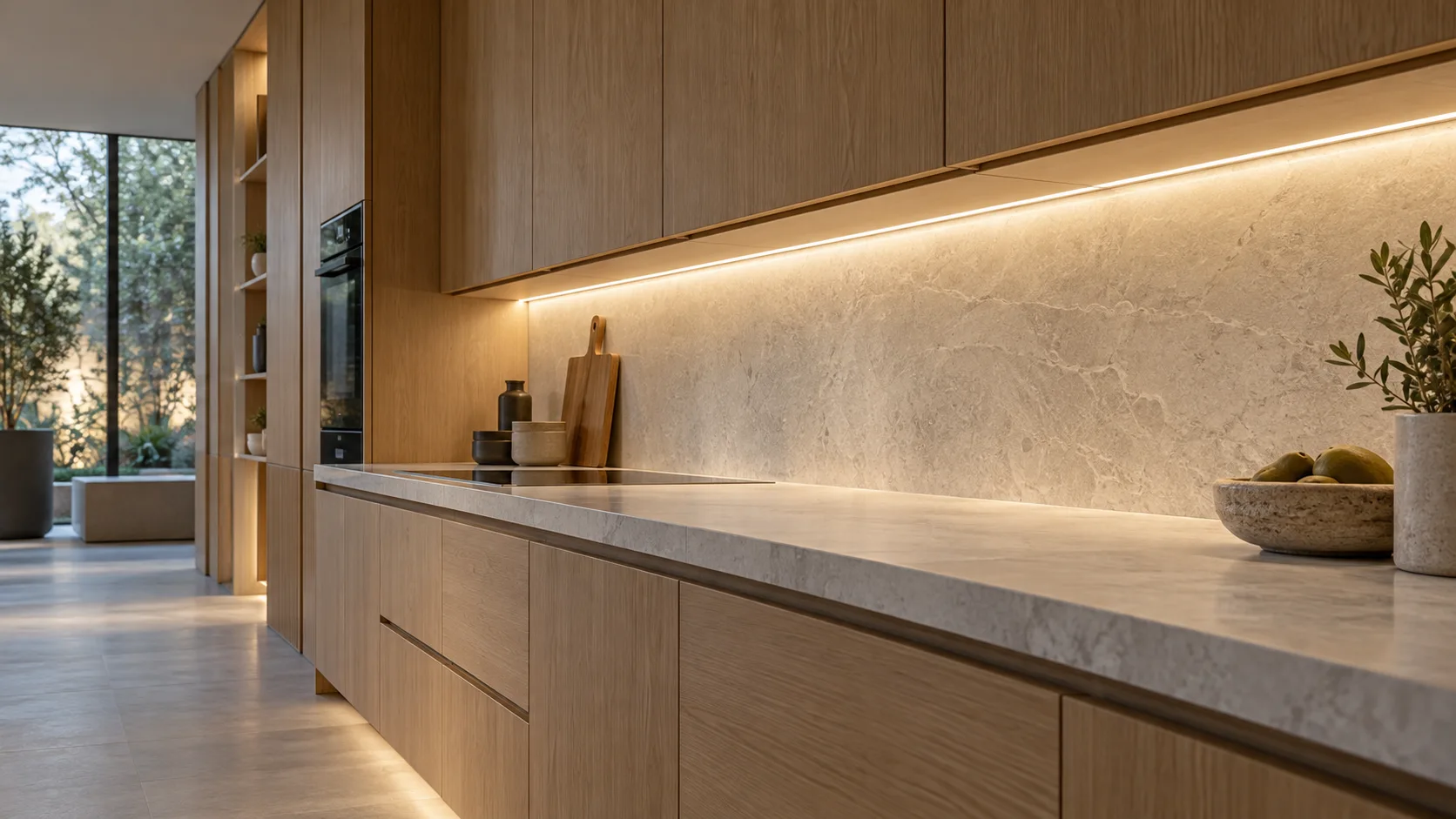
Inspect the actual light-source construction
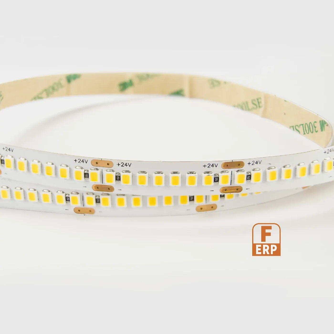
A close view of an LED strip helps distinguish the board, packages and electrical sections. Use the selected model drawing for its dimensions and cutting interval.

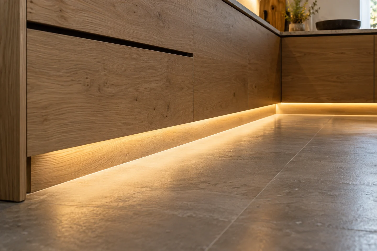
Treat the plinth, floor finish, corners and cleaning exposure as one installation detail.
Discuss this assemblyTreat the plinth, floor finish, corners and cleaning exposure as one installation detail.
Draw plinth runs, corners, end returns and removable panels. Identify cleaning exposure and the floor finish; reflected source images can become visible on polished surfaces.
Plan feeds and corner joints so a plinth panel remains removable. Check the treatment and rating of cut ends, leads and connectors as well as the strip enclosure.
Inspect light continuity and source visibility from seated and standing sightlines. Record each joint, service point and intended cleaning environment with the approved detail.
DESIGN DECISIONS
Toe-kick lighting is most convincing when the source disappears and only the reflected line remains. Recess depth, floor gloss and the plinth return can change the result dramatically. Treat cleaning exposure and removable access panels as design inputs, not details to resolve after the light has been cut.
| Decision | Required input | Review with the sample |
|---|---|---|
| Floor reflection | Actual floor sample and seated sightline | Set back the source until direct LED images are controlled |
| Corners | Internal and external return dimensions | Specify joints and lead exits instead of bending a rigid profile |
| Protection | Cleaning method and termination positions | Assess the assembled strip, connectors and cut ends together |
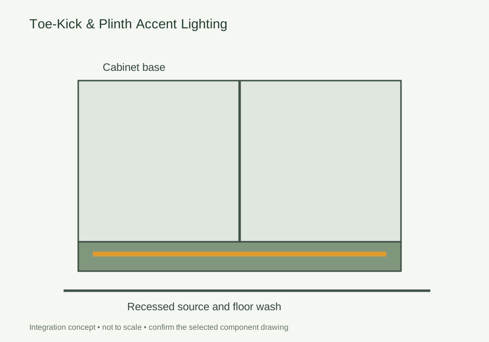
Use this concept to mark mounting positions, cable paths and service clearances on your fixture drawing. Dimensions and component references belong on the project drawing before machining.
Photographs support the adjacent selection decisions. The exact delivered components and their performance need their own drawings, documents and sample review.
A close view of an LED strip helps distinguish the board, packages and electrical sections. Use the selected model drawing for its dimensions and cutting interval.
Use these selection questions in the assembly brief. Confirm availability, compatibility and performance for the proposed configuration.
Specify the lit sections, corner transitions and feed schedule by cabinet run.
If this description appears in the brief, verify the actual IP54-rated parts and the completed joint detail; do not read it as an immersion rating.
Compare the source with the fixture dimensions and intended light effect. A complete supply schedule also identifies the profile, controls, connectors and the work included in the assembly.
This detail includes components beyond an LED strip. The catalogue does not identify a complete, approved kit for this arrangement. Send the fixture section and required operation so the source, control and mechanical interfaces can be reviewed together.
Compare catalogue light sources → Review the wider furniture system →
Discuss components for this detailState the quantity basis and open decisions. A labelled assembly schedule keeps design, purchasing and installation working from the same reference.
FREQUENTLY ASKED QUESTIONS
Practical answers for the furniture drawing, sample review and purchasing brief.
Ask a project question →No. A component rating does not establish the protection of cut ends, connectors or a finished assembly. Define the exposure and ask for evidence for the supplied configuration.
Put the disconnect point where the panel can be removed without pulling on the LED section. Record the feed and connector positions on the installation drawing.
Show every corner and removable panel on the cutting schedule. Put disconnects where service access remains possible and identify the termination detail. Review cleaning exposure for the completed assembly, including its connections.
Include Drawing revision and finished dimensions, Module quantity and order basis, Source, profile and control references. Add quantities by furniture module and identify the configuration or sample already selected. This gives the drawing review a defined scope before pricing and assembly approval.
CONTINUE THE SPECIFICATION
Use the wider furniture brief to coordinate this lighting detail with adjacent modules and project teams.
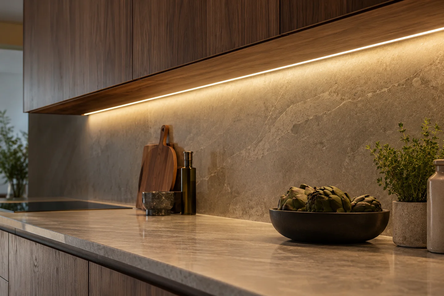
Set the light line around the worktop and backsplash. Check the channel angle, diffuser, hand position and feed location on the cabinet drawing.
View the solution →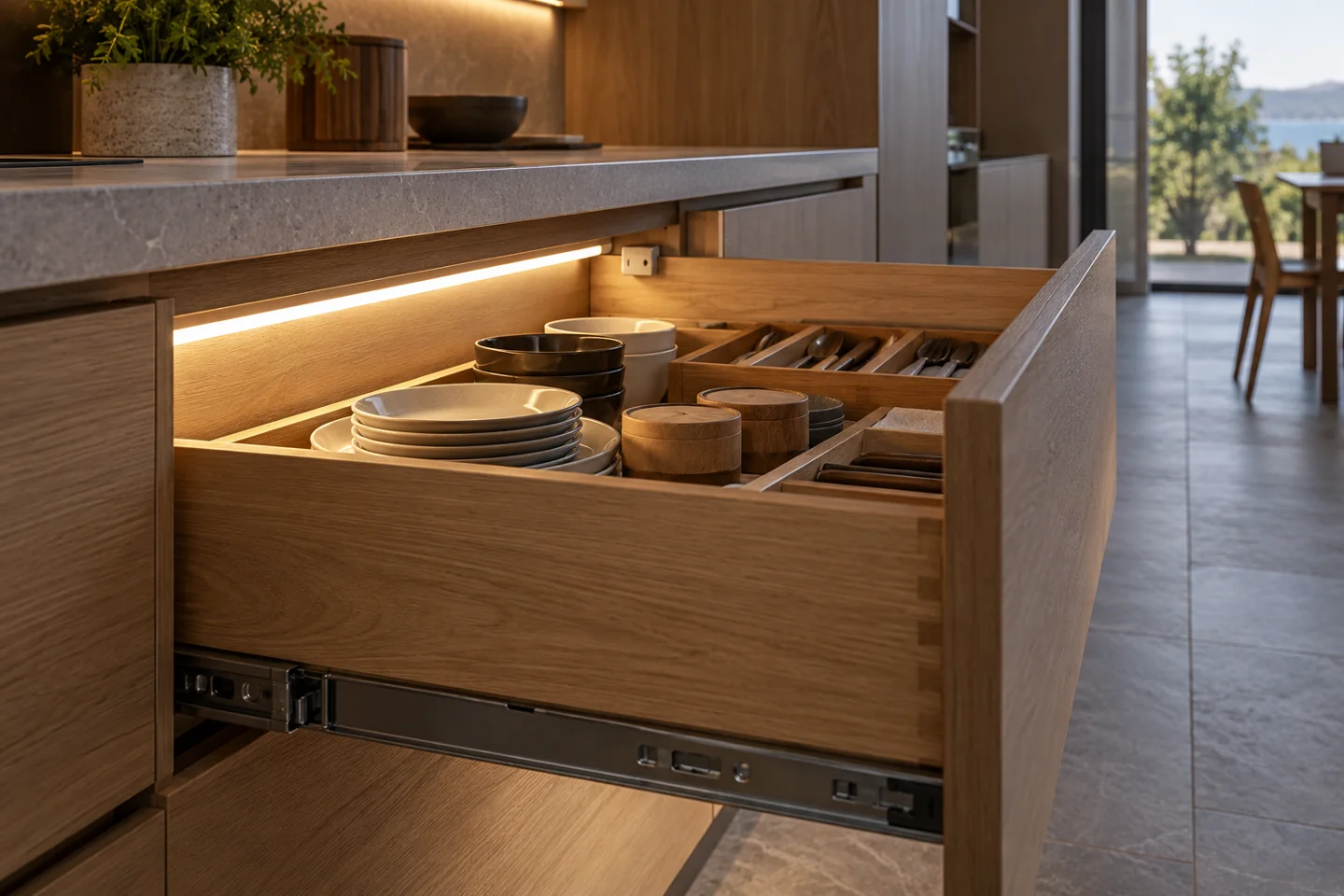
Keep illumination out of the drawer runner envelope. Plan how the light switches, how the cable moves and how a replacement can be reached.
View the solution →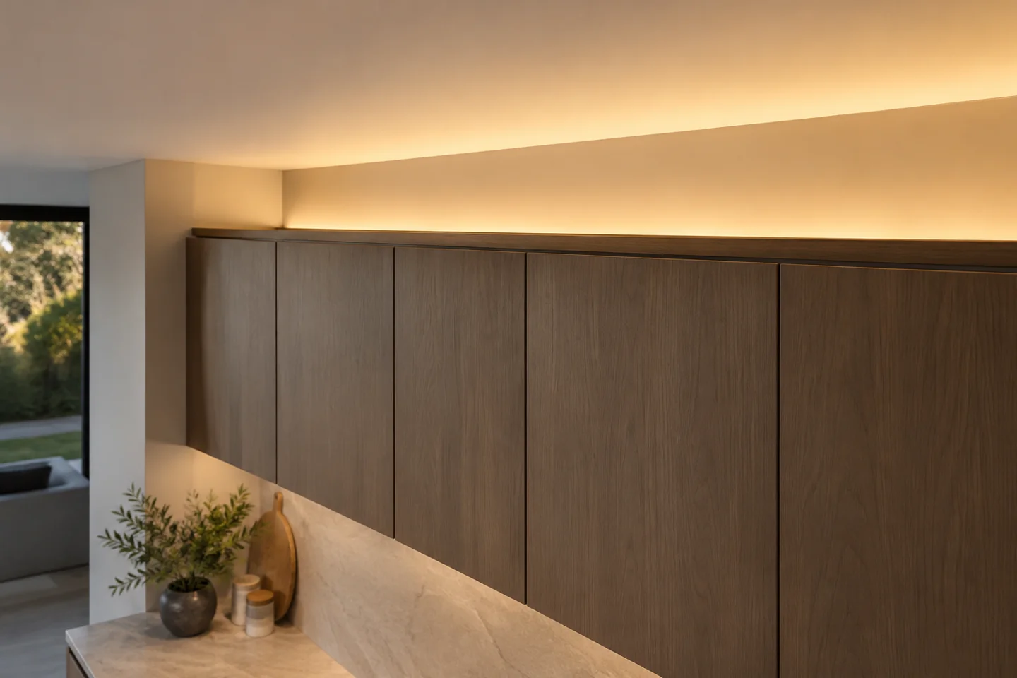
Define the ceiling reveal and the access route for the driver and distribution leads.
View the solution →