Under-Shelf Recessed Joinery Lighting
Coordinate machining, light direction and the shelf support before the section is released for cutting.
View the solution →

Repeatable lighting modules for shelves, headboards and fitted furniture. Keep the cut schedule, connectors, driver locations and packing list tied to the joinery drawings.
Discuss this assemblyRepeatable lighting modules for shelves, headboards and fitted furniture. Keep the cut schedule, connectors, driver locations and packing list tied to the joinery drawings.
Coordinate machining, light direction and the shelf support before the section is released for cutting.
View the solution →
Plan the ambient effect around seated and sleeping eye positions, with switches and service points within reach.
View the solution →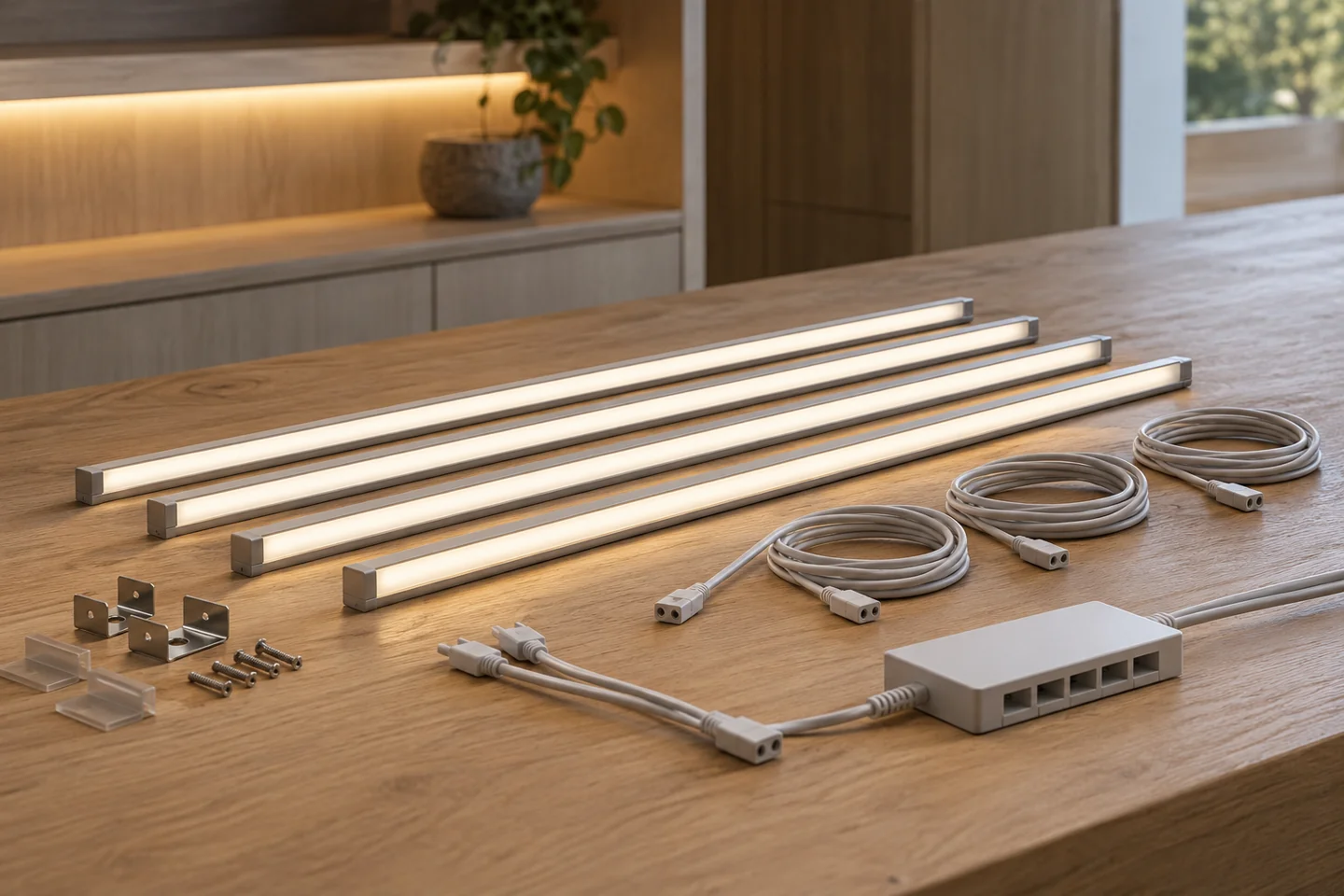
Use an assembly schedule to link each section to the correct harness branch and package.
View the solution →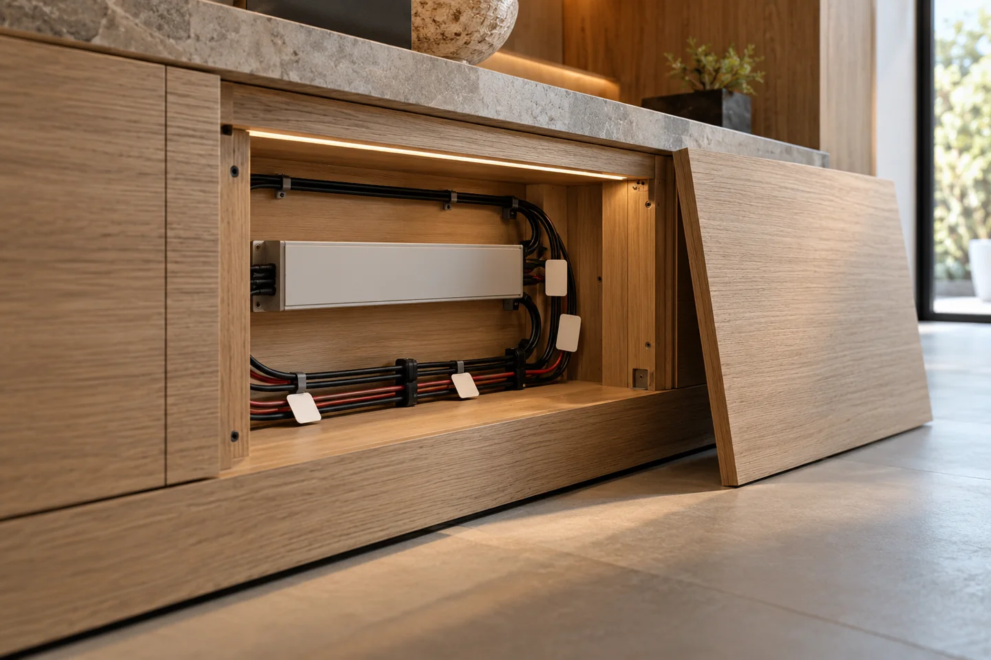
Added as the twentieth subscene: reserve an accessible electrical compartment and a route for replacement without dismantling finished joinery.
View the solution →Work from furniture sections and room-type schedules. Identify the lighting module for each shelf, headboard or bed base, then assign the leads, control zone and service access. Packing by furniture module helps purchasing compare the assembly work included in each quotation.
DESIGN DECISIONS
A custom joinery & hospitality furniture brief should distinguish the visible effect from the assembly needed to achieve it. Start with the furniture sections and the way the space is used. Each detail below addresses its own installation, control and maintenance decisions; it should not inherit a specification simply because it sits in the same room.
| Decision | Required input | Review with the sample |
|---|---|---|
| Under-Shelf Recessed Joinery Lighting | Coordinate the groove with panel thickness, supports, fasteners and the front edge. Tie machining dimensions to the selected profile revision and intended light direction. | Inspect the assembly with a representative loaded shelf and finish. Check glare and visible connections, then retain groove, fixing and lead details for the other shelf sizes. |
| Headboard & Floating Bed Accent Lights | Show pillow and seated eye positions, reveal depth, floor clearance and approach paths. Mark switches and the driver location after surrounding furniture is installed. | Check the light at intended dimming levels from sleeping and seated positions. Test sensor activation from both sides where required and record the validated zone behaviour. |
| Modular Quick-Connect Harness System | Create a module schedule for light sections, sensors, drivers and leads. Include connector references, pin assignments, lengths and labels, and distinguish preassembled parts from site operations. | Trial the kit in its intended assembly sequence. Check labels, strain-free connections and control operation, then resolve open interfaces before authorising repeated kitting. |
| Driver Concealment & Service Access | Reserve the driver, junction, cable bend and ventilation space in the drawing. Show the replacement path after adjoining joinery and finishes are complete. | Demonstrate access and replacement in a representative furniture section. Check disconnection, identification and the service panel detail, then retain these with the final assembly schedule. |
Use the scene images above with the corresponding installation notes below. A lighting detail should not inherit an unrelated wiring or mounting arrangement.
Coordinate the groove with panel thickness, supports, fasteners and the front edge. Tie machining dimensions to the selected profile revision and intended light direction.
Review this detail →Show pillow and seated eye positions, reveal depth, floor clearance and approach paths. Mark switches and the driver location after surrounding furniture is installed.
Review this detail →Create a module schedule for light sections, sensors, drivers and leads. Include connector references, pin assignments, lengths and labels, and distinguish preassembled parts from site operations.
Review this detail →Reserve the driver, junction, cable bend and ventilation space in the drawing. Show the replacement path after adjoining joinery and finishes are complete.
Review this detail →Photographs support the adjacent selection decisions. The exact delivered components and their performance need their own drawings, documents and sample review.
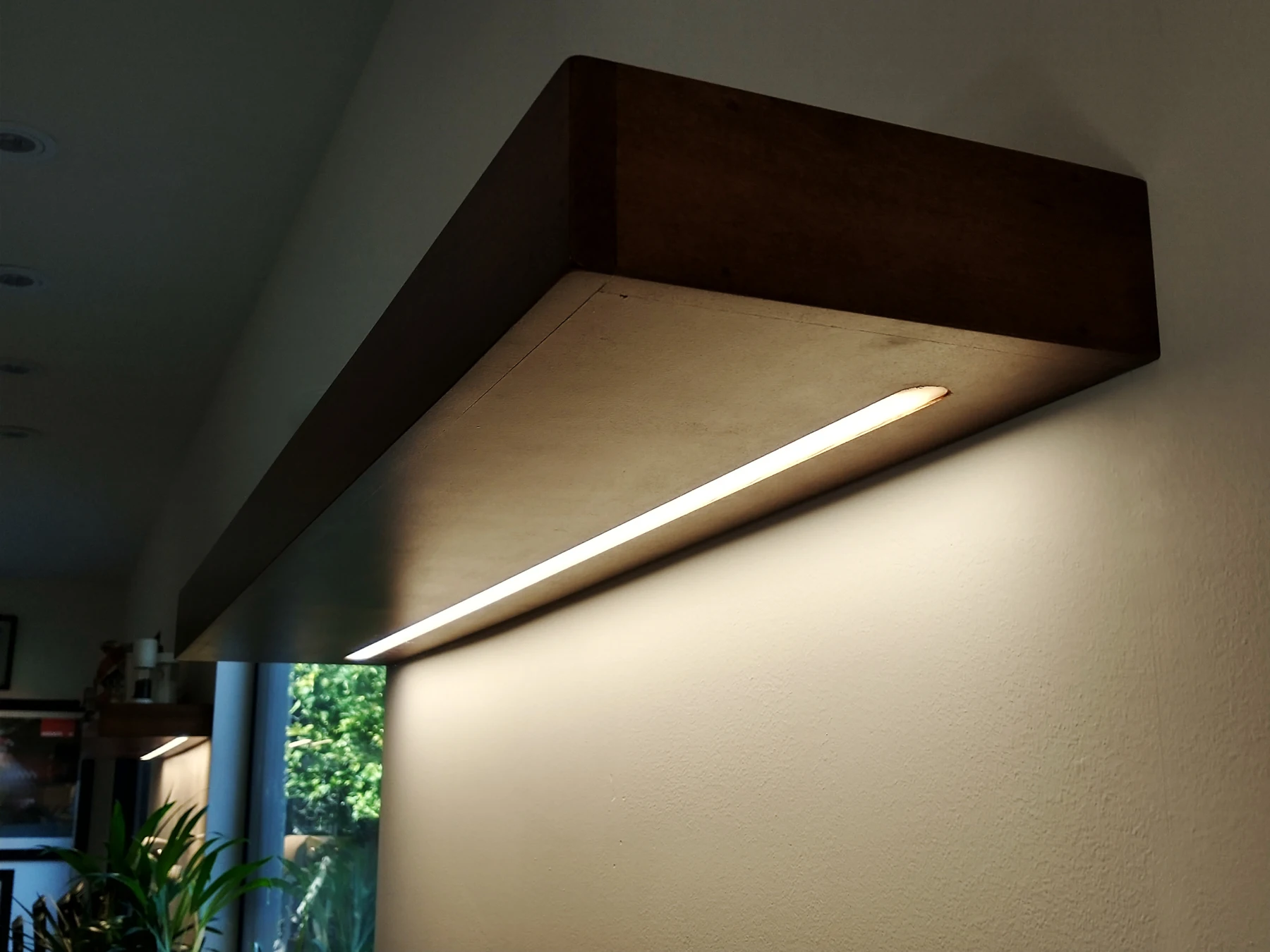
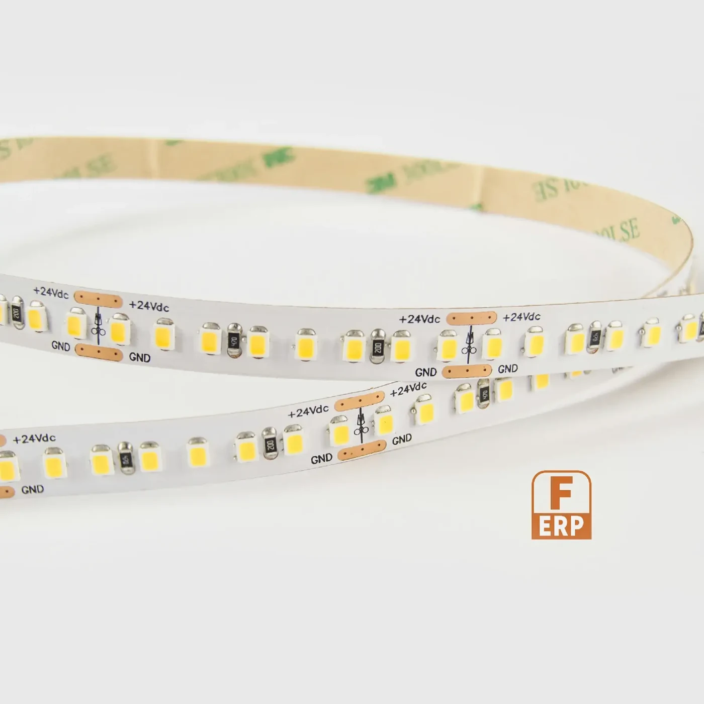
The photograph shows a completed under-shelf installation. Compare the source setback and reflective surfaces; it does not document the LED model or measured output.
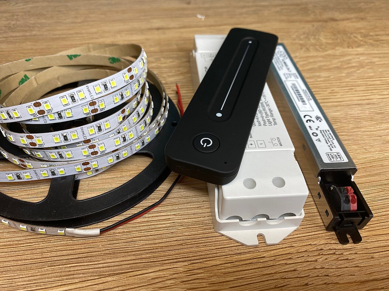
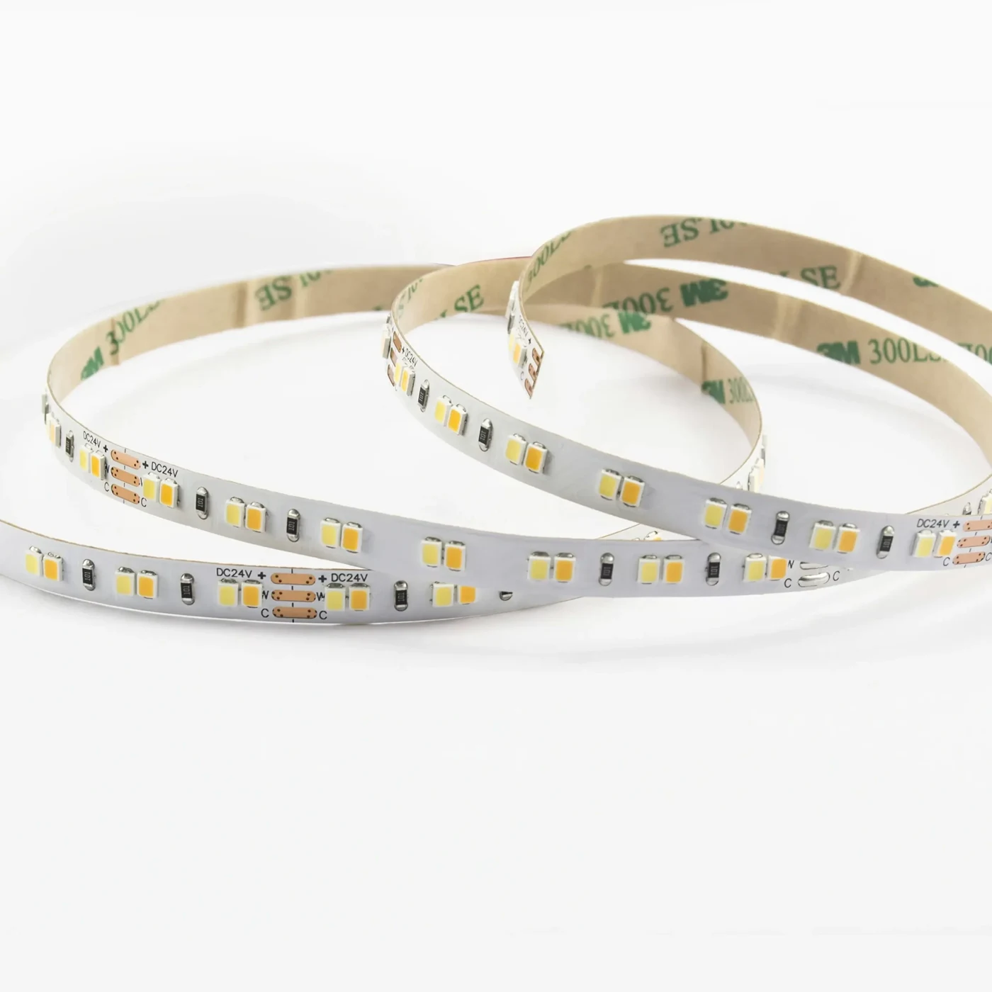
The photograph shows a strip, controller and supply together. Confirm the selected assembly’s voltage, load, control interface and service envelope; this is not a PIR or cascade controller specification.
Use these selection questions in the assembly brief. Confirm availability, compatibility and performance for the proposed configuration.
Check the groove against panel thickness and fixing hardware.
Consider accessible surface mounting when the panel cannot accept a recess.
Review the finished shadow gap and source visibility from normal sightlines.
Agree the reveal, reflecting finish and dimming behaviour in the room mock-up.
Check sensor coverage, timeout and whether movement on either side should activate the light.
List finished length, lead orientation and identification for every module.
Confirm branch current, polarity and connector mating before assembly.
Define which connections are preassembled and which remain site operations.
Check enclosure dimensions, cable strain relief and service access alongside the driver and protection requirements.
Compare the source with the fixture dimensions and intended light effect. A complete supply schedule also identifies the profile, controls, connectors and the work included in the assembly.
State the quantity basis and open decisions. A labelled assembly schedule keeps design, purchasing and installation working from the same reference.
FREQUENTLY ASKED QUESTIONS
Practical answers for the furniture drawing, sample review and purchasing brief.
Ask a project question →Use a dated bill of materials and module schedule with cut lengths, cable exits and connector references. Keep the approved sample identifier with those documents. List left/right versions and room variants explicitly instead of leaving installers to modify a standard kit.
Only if its electrical and mechanical interfaces suit every proposed branch. Check polarity, pin allocation, wire size, load and mating series. Similar-looking plugs are not evidence of compatibility.
Identify the driver, controls, distribution points and replacement route for the light section. Coordinate access with the furniture and electrical teams. Draw how a failed component can be removed without cutting permanent finishes.
Approve the representative furniture detail, wiring schedule, selected light appearance and agreed inspection points. Confirm which components are preassembled and which connections remain on site, then list the quantities by module and room variant.
CONTINUE THE SPECIFICATION
Use the wider furniture brief to coordinate this lighting detail with adjacent modules and project teams.
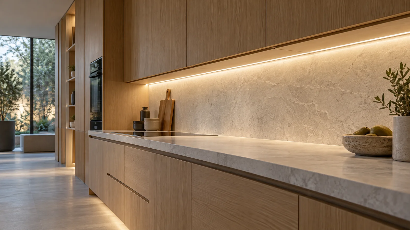
Worktop light, concealed cable routes and coordinated sensors—planned as one cabinet assembly, with cut lengths and connectors identified for each module.
View the solution →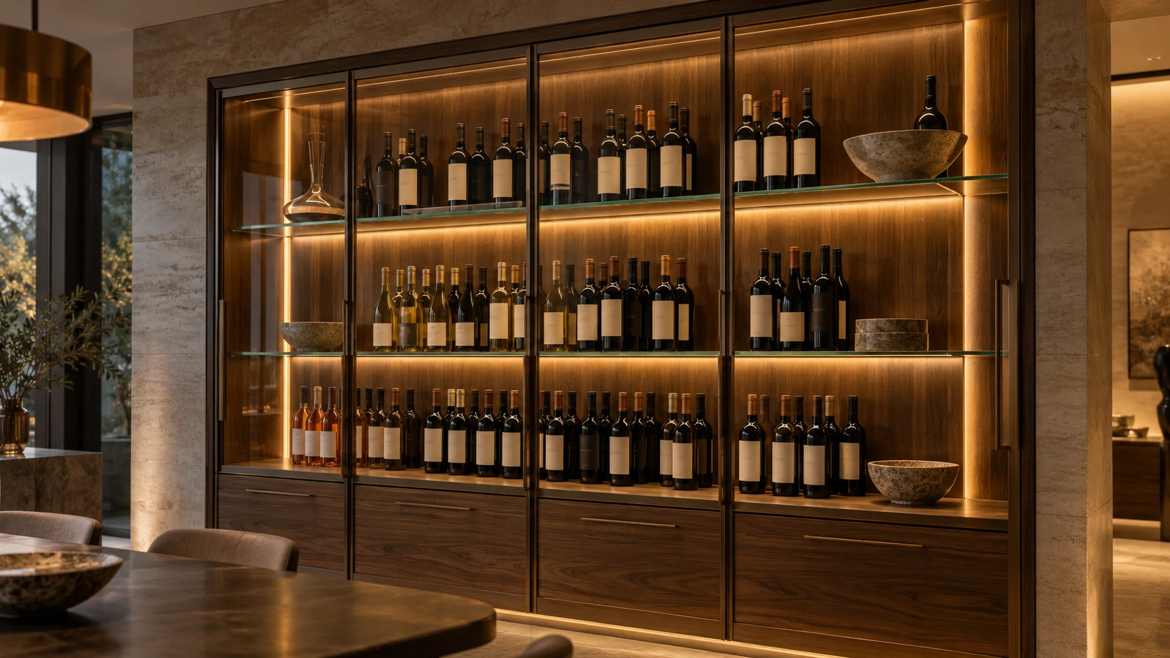
Quiet, warm light for bottle displays and glazed cabinets. Resolve shelf edges, reflections, cable visibility and thermal conditions before approving the assembly.
View the solution →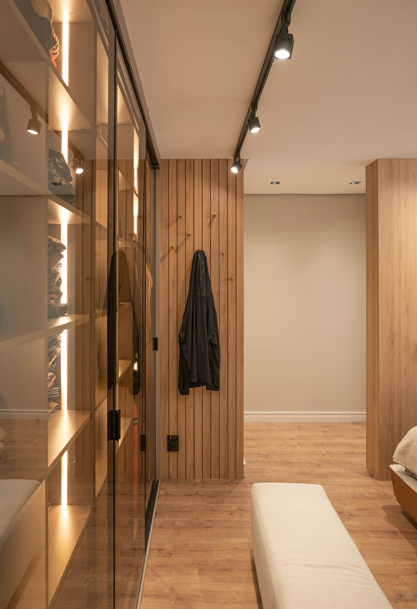
Integrated light for hanging rails, vertical panels and shoe or bag shelves. Match sensing, cable routes and light colour to each compartment.
View the solution →