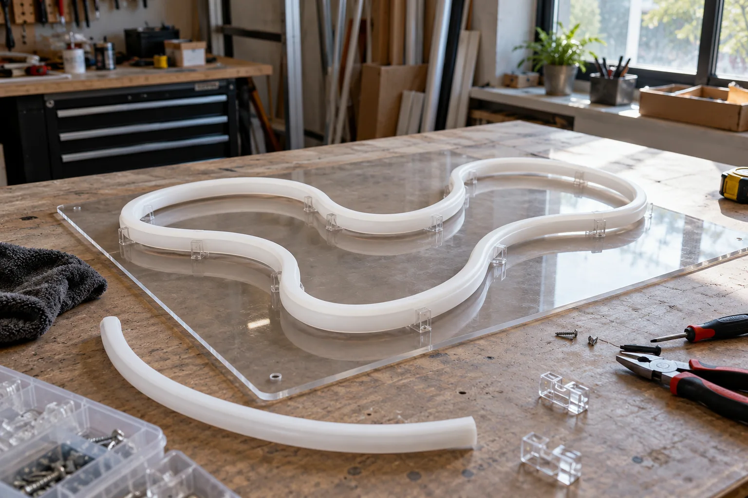
AI-generated concept illustration for bend, clipping and backing discussions; not a factory photograph or an approved fabrication drawing.
Price manufacturable light sections with the difficult letters resolved
Sign manufacturers need a neon flex enquiry that connects the graphic designer’s line to the physical sign on the backing. Letter size, crossing strokes, cable passages and mounting orientation all affect the section plan. When sourcing LED neon sign sections, identify a suitable product geometry and define the delivery scope: source material, terminated lengths or another agreed assembly. With scaled artwork and a clear installation brief, the sign maker can compare equivalent offers and evaluate the details that matter before committing to the full set of letters or repeated signs.
Letterforms and tight returns
For neon flex letter fabrication, separate the visual stroke from the product’s centreline and mounting envelope when converting artwork. Small counters, script joins and returning strokes may need changes to the graphic or a different section layout. Flag those features first so the customer can approve any visible design adjustment before a complete sign is priced as final.
Backing, cable passages and support
Coordinate light sections with holes, fasteners and cable routes on the neon flex sign backing drawing. Concealed neon sign lead exits still need an accessible fabrication method and a route behind the backing. Identify the sign face and installation orientation clearly so the supplier’s termination proposal can be reviewed against the assembled backing rather than only the artwork.
Repeated logos and multi-piece compositions
For a branded sign programme, give repeated sections common identifiers while distinguishing mirrored or orientation-specific parts. Map separate letters and graphic elements to the intended electrical groups. Keep any locally assembled connections visible in the supply schedule so the sign workshop can check a complete set before the parts leave for installation.
Installation and component references.
Photographs support the adjacent selection decisions. The exact delivered components and their performance need their own drawings, documents and sample review.
External reference photograph. Not a BEXLIGHT installation or a supplied component approval. Reproduced unchanged. Photo: NEON CASA · License.
Plan the visible light route
This external decorative LED reference illustrates a shaped light route. Bend direction, supports, terminations and power requirements remain specific to the selected product.
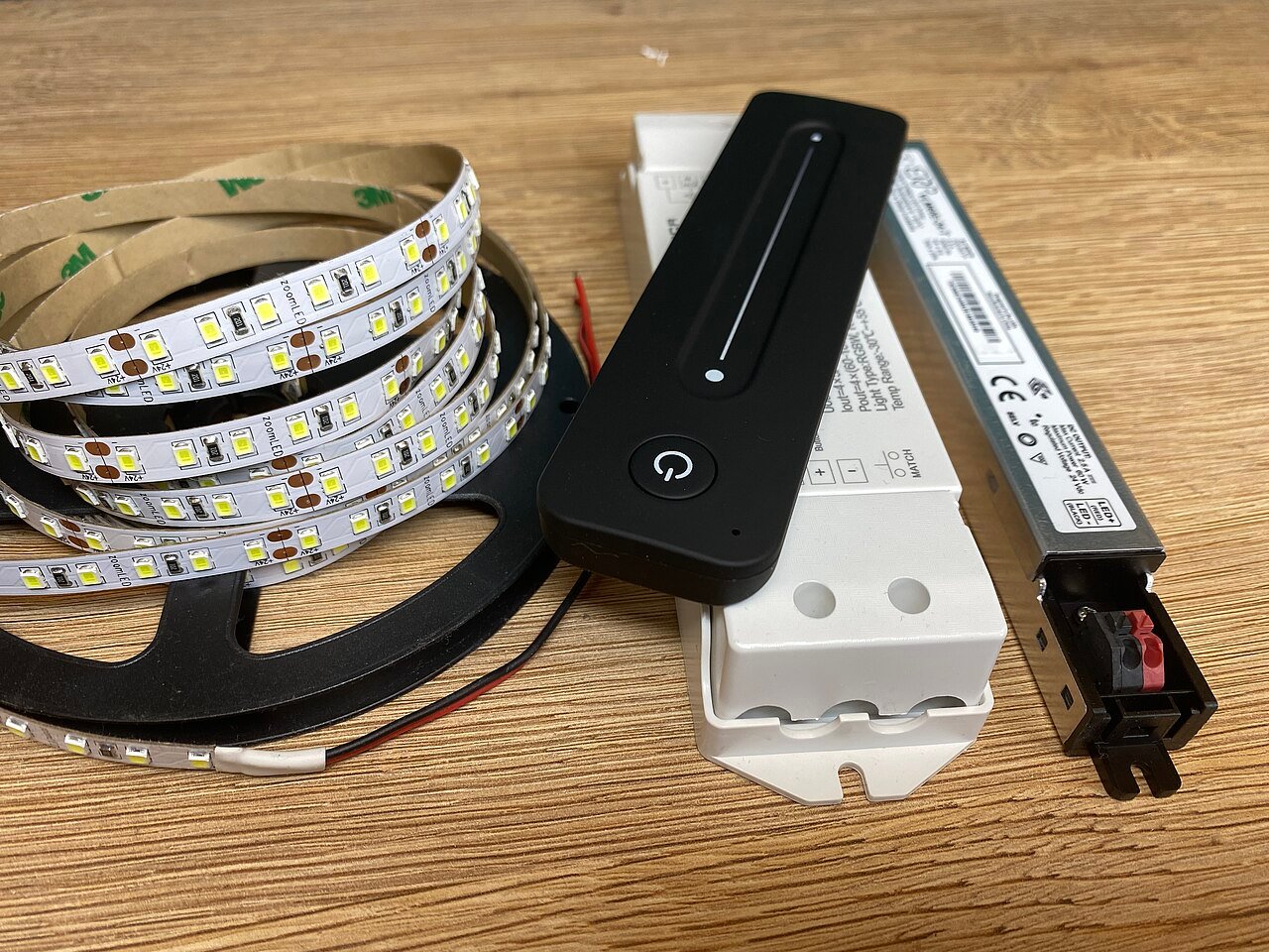
External reference photograph. Not a BEXLIGHT installation or a supplied component approval. Reproduced unchanged. Photo: MickelPL · License.
Treat the driver and control as separate components
The photograph shows a strip, controller and supply together. Confirm the selected assembly’s voltage, load, control interface and service envelope; this is not a PIR or cascade controller specification.
A source that fits the finished detail.
Compare the light line, assembly envelope and control requirements together. The routes below are starting points for a specification discussion.
Catalogue reference SR006-1004TF-140P2835IP67; final configuration requires review.
For directly visible strokes with a compatible bending plane
Consider Neon Flex where the illuminated line is itself the graphic element. Compare exact cross-sections against the scaled letterforms, mounting detail and permitted bending geometry before finalising stroke spacing, joints and finished section lengths.
Not every letter can be formed as one piece. Cut intervals, end fittings and lead exits must be included in artwork conversion.
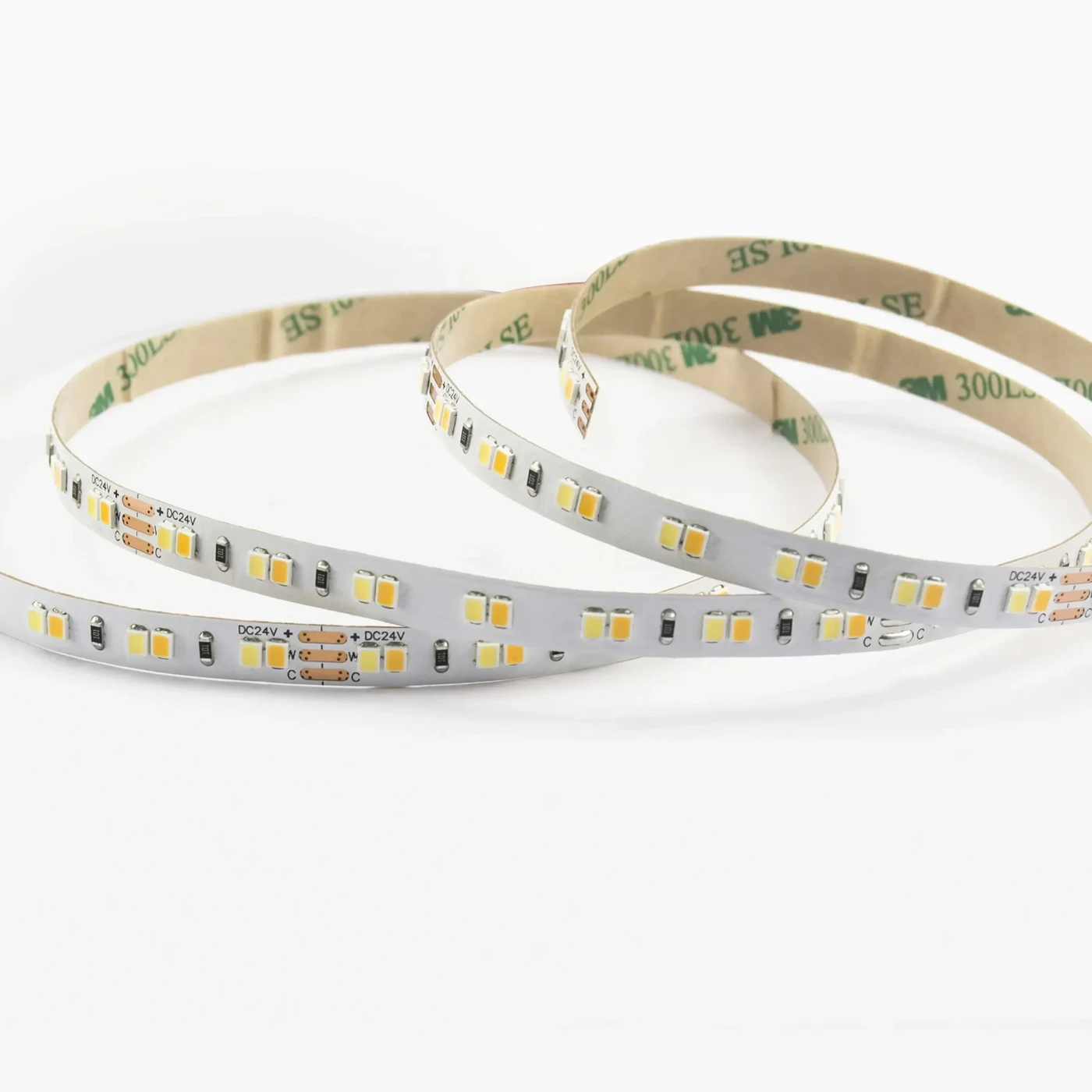
Catalogue reference SR005-140P2835IP20TW; final configuration requires review.
For selected concealed details within a sign enclosure
Consider an SMD strip assembly for an enclosed or indirect linear sign detail where the structure provides the optical path and suitable mounting. Evaluate a representative enclosure section rather than treating it as interchangeable with visible Neon Flex.
A strip source is not an automatic substitute for a luminous stroke. Review the enclosed sign’s optics, wiring and finished assembly separately.
Use the fixture drawing, component documentation and a representative assembly to turn the visual brief into a repeatable specification.
01
Identify the illuminated face and bending plane
Mark how the line must turn relative to its lit surface. Labels such as side-bend and top-bend are useful only when tied to the manufacturer’s illustration for the selected model. Check the tightest curves against the permitted geometry. Do not force a strip into a letterform that needs bending in a different plane.
02
Schedule active sections and lead exits
Number each light section on the artwork. Show the required visible length, cut interval, end allowance, joint and cable exit. A letter outline can require several separately made pieces. Keep finished assembly length separate from active illuminated length so end fittings do not appear as an unplanned gap.
03
Coordinate the backing and mounting
Include mounting hardware, fastener locations and cable passages in the fabrication drawing. Check how each section is installed and replaced on the backing. For an exposed sign, obtain an actual environmental brief and verify the permitted finished terminations; an uncut-product rating is not a substitute for an approved completed sign detail.
04
Approve a difficult feature first
Make a sample of a tight curve, joint or small letter using the proposed assembly method. Review line continuity and mounting distortion under the intended viewing conditions. Keep the accepted drawing revision, product identity and termination process with the order. This avoids approving a straight sample for a sign whose difficult feature is a curved character.
From an initial brief to a controlled assembly.
Send dimensioned artwork, the illuminated-face direction, exposure requirements and sign quantities. Include any existing backing or enclosure constraints. Exact bend and cut values must come from the selected model, not a generic neon-flex guide.
Decision
What to check
Record or boundary
Artwork conversion
Section IDs and permitted curves
Scaled fabrication drawing
Termination
Active length, end allowance and lead direction
Approved end detail
Assembly
Backing, supports and replacement path
Fabrication sample
Scaled vector artwork
Illuminated face and mounting orientation
Backing and cable passage drawing
Exposure and installation conditions
Source or terminated-section scope
FREQUENTLY ASKED QUESTIONS
Application FAQ
Selection, integration and repeat-supply questions for this application.
01What artwork files make a neon flex enquiry useful?
Provide scaled vector artwork where available, plus the intended overall dimensions and the illuminated face orientation. Identify features that must remain visually exact and those that can change during fabrication review. Include the backing and cable-entry constraints so the proposed section plan can be assessed as a sign assembly rather than a line drawing alone.
02How do we handle a letter that exceeds the selected product’s bend geometry?
Return the feature to the artwork and fabrication review instead of forcing the source into shape. Possible approaches include changing the letter detail, splitting it into approved sections or reviewing a different product geometry. The sign customer should see the resulting visible treatment before production, especially where additional ends alter the continuity of a stroke.
03Can a terminated source be ordered to the exact drawn stroke length?
Ask the supplier to distinguish active illuminated length from finished assembly length and to show the permitted cut and end arrangement. Artwork dimensions do not always translate directly into a manufacturable active section. Agree the feasible result on the section drawing and reference that drawing in the order for each letter or graphic element.
04What changes for an exposed sign compared with an indoor installation?
The enquiry needs the actual exposure and mounting conditions, including the location of connections and equipment. Request documentation relevant to the exact source and finished terminations proposed. The sign maker and responsible project parties still need to review the completed sign assembly; a source description alone does not define suitability for every installation environment.
Share the fixture or route drawing, quantities, target market and the decisions still open. Include your company and whether you are preparing a sample, a project or repeat production.