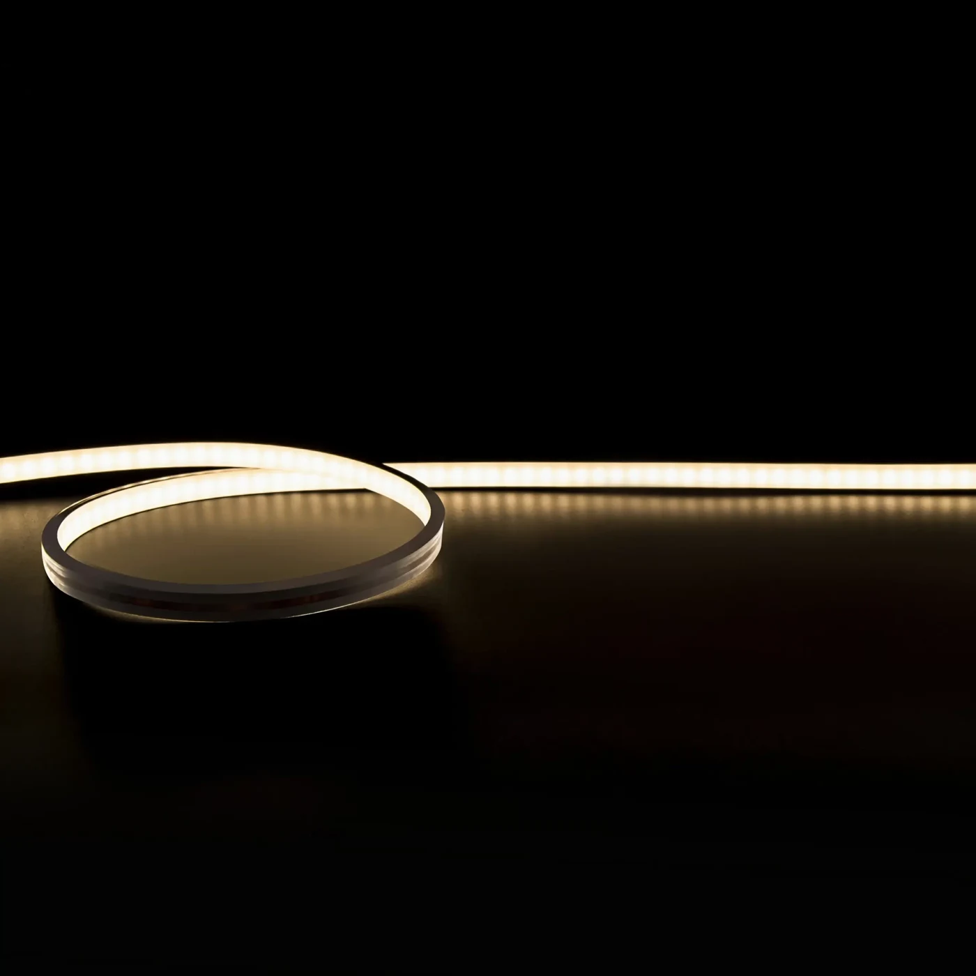
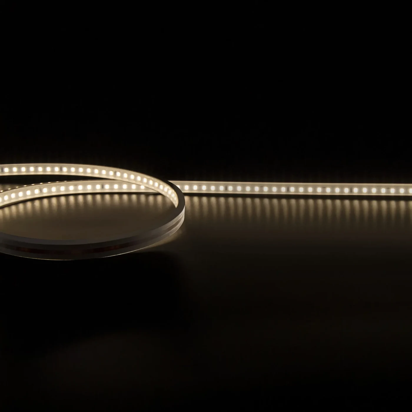
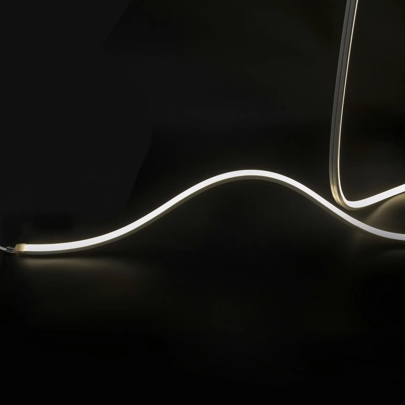
Route & bending
Draw the corners, curves and transitions. Check this model’s bending direction and minimum bend diameter before approving the route.

Neon Flex · BEXLIGHT
Model SR006-1616T-140P2835IP68
A silicone-enclosed LED light line for shaped and architectural details. Choose the bending direction and enclosure size to match the route of your installation.
For fixture development, project supply and repeat B2B orders. Include the quantity and intended configuration in your enquiry.
Work from the intended route, bending direction and termination position. A silicone neon flex is selected as an assembly: its body size, mounting arrangement and feed cable need space as well as the visible light line.
Coordinate this model with the selected profile, diffuser, driver, sensors and quick-connect harness. Discuss Pre-Cut Custom Lengths and Custom Assembly & Kitting against the drawings; a catalogue strip alone is not a ready-to-install kit.
MODEL DATA
Match the selected configuration to your order and fixture drawing. Options and catalogue ranges describe available configurations rather than simultaneous ratings.
Model reference
SR006-1616T-140P2835IP68
| Parameter | Value / options |
|---|---|
| Luminous output | 600 lm/m |
| Power per metre | 14.4 W/m |
| LEDs per metre | 140 |
| Supply voltage | 24V |
| Dimensions | 16*16*5000mm |
| Cut interval | 50mm |
| Minimum bend diameter | >60mm |
| Copper foil | 3OZ |
| Protection | IP68 |
| Colour temperature options | 2700, 3000, 4000, 5000 |
| CRI options | 80Ra, 90Ra, 95Ra |
| LED type | 2835 |
Retained for reference; confirm options for the supplied configuration.
| Power(W/m) | 9.7-14.4 |
|---|---|
| Voltage | 24V |
| Lumen output | 600-999 |
| CCT | 2700, 3000, 4000, 5000 |
| CRI | 80Ra, 90Ra, 95Ra |
| LED Type | 2835 |
| LEDs/m | 140LEDs/m |
| Dimension | 16*16*5000mm |
| Cut unit | 50mm |
| Bend Diameter | >60mm |
| Copper Foil | 3OZ |
| IP Rating | IP68 |
| Warranty | 3-5 years |
Use the model information alongside your fixture and installation requirements. The sample should answer the questions that a catalogue image cannot.
Draw the corners, curves and transitions. Check this model’s bending direction and minimum bend diameter before approving the route.
Allow for mounting clips or channels, end caps, cable exits and service access. A body IP rating does not establish the rating of a cut and reassembled installation.
Confirm the actual lengths, input voltage and controller arrangement. Validate colour and dimming on a representative sample before releasing a repeat order.
This enclosed flexible source is a candidate for indirect light routes. Check its actual bend direction, body section and termination allowance against the drawn route. These are application planning routes, subject to configuration and sample review.
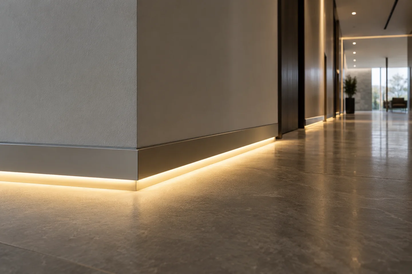
Plan a continuous line through doors, corners and finishes with identified feed points and replaceable light sections.
View the solution →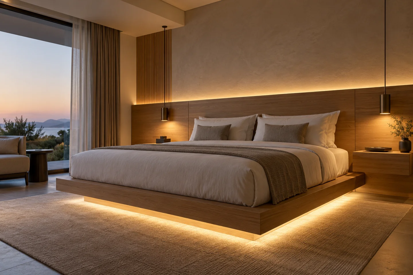
Plan the ambient effect around seated and sleeping eye positions, with switches and service points within reach.
View the solution →TECHNICAL SUPPORT
Need a model datasheet, dimensional drawing or wiring information? Send the model reference and the configuration you are considering so the appropriate documents can be identified.
For a quotation, include the application, quantity and unit, section lengths, colour requirement, target market and any fixture drawings.
Request documents or discuss this modelFREQUENTLY ASKED QUESTIONS
Model selection, installation scope and the information needed for a B2B quotation.
Ask a project question →The model record lists 24V. Match the selected configuration to the driver output and confirm the complete branch load, wiring and control arrangement. Do not connect a low-voltage strip directly to mains power.
The listed cut interval is 50mm. Work to the permitted cut marks and allow space for the termination, cable exit and mounting detail. Finished assemblies need a length schedule; the cut interval does not mean every requested dimension can be supplied exactly.
This is the protection value shown for the catalogue source configuration. Check the intended exposure, cut ends, connections and mounting assembly separately. A reel rating does not automatically apply to a cut and reassembled lighting system.
Confirm the model’s bending direction and minimum bend diameter, then mark curves, end caps and cable exits on the route drawing. Do not twist the body to follow a second bending plane or assume another neon model uses the same mounting section.
This page identifies the light source. A complete assembly also defines the profile, diffuser, driver, controls and harness. Send the fixture drawing and quantities to scope pre-cut lengths, prewired connections and packing by module.
Quote SR006-1616T-140P2835IP68 and specify the selected colour, finished lengths, feed exits, quantity and unit. Add the application drawings, target market and required documents. Catalogue options and ranges need to be resolved into one identifiable order configuration.
Check the individual configuration and physical dimensions before substituting a model.