
Cut-interval planning worksheet
Plan active strip length from a verified cut interval and an explicit end allowance.
Updated October 26, 2026
Discuss your requirementOn this page
Plan active strip length from a verified cut interval and an explicit end allowance. This worksheet counts permitted-length segments; it does not approve a powered run, bending detail, termination process or resealed ingress rating.
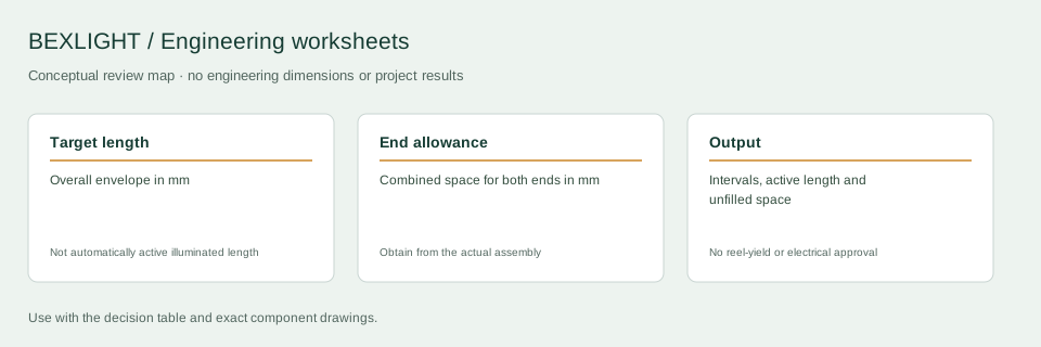
Decision and input record
| Decision | What to check | Record or boundary |
|---|---|---|
| Target length | Overall envelope in mm | Not automatically active illuminated length |
| End allowance | Combined space for both ends in mm | Obtain from the actual assembly |
| Output | Intervals, active length and unfilled space | No reel-yield or electrical approval |
Start with the complete assembly envelope
Enter the target overall length in millimetres and the combined allowance for both ends. That allowance must come from the actual connector, soldering, end-cap or assembly drawing. Available active space = target length minus the combined end allowance. Do not assume an unlit fitting occupies no space.
Use the exact model’s cut interval
The worksheet uses the largest whole number of cut intervals that fits in the available active space. Interval count = floor(available space / cut interval). Active length = count × cut interval. Planned assembly length = active length + declared allowance. Unfilled space = target length minus planned assembly length. Check the selected product instructions before transferring any count to production.
Worked dimensional example
For hypothetical inputs of 1000 mm target length, 30 mm total end allowance and 50 mm cut interval, available space is 970 mm. Nineteen intervals provide 950 mm of active source. With the declared allowance, the assembly occupies 980 mm and leaves 20 mm unfilled. For ten identical pieces the scheduled active source total is 9.5 m.
What the quantity total omits
The total is active length across pieces. It does not calculate reel nesting, unusable remnants, cutting kerf, process scrap, yield, matching stock or transport losses. It cannot determine whether several pieces may share a feed. Record the proposed section and termination drawing, then obtain the relevant assembly and electrical approvals before ordering cut-to-length production.
What to include in a technical inquiry
Send the target section drawing, verified cut interval, end details and required piece quantity. An allowance entered as zero is an explicit assumption that still needs to match the real assembly.
Discuss the application and supply scope
Continue with the relevant detail
Tell us about your installation
Include the application, section lengths, quantity and installation conditions.
Discuss your requirement