

DC feed-cable voltage-drop calculator
Estimate DC feed-cable loop resistance, voltage drop and cable dissipation using documented conductor data. Keep strip loss and safety checks separate.
Updated October 26, 2026
Discuss your requirementOn this page
Estimate voltage drop in a simple equal-conductor DC cable loop. Use resistance data supplied for the actual conductor. The result covers the feed cable, not the strip, joints, ampacity or protective-device selection.
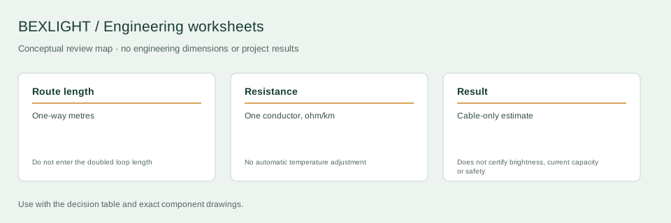
Decision and input record
| Decision | What to check | Record or boundary |
|---|---|---|
| Route length | One-way metres | Do not enter the doubled loop length |
| Resistance | One conductor, ohm/km | No automatic temperature adjustment |
| Result | Cable-only estimate | Does not certify brightness, current capacity or safety |
Model only the stated circuit
The worksheet assumes one outgoing and one return conductor, each with the entered one-way length and conductor resistance. Enter metres for length and ohm/km for one conductor. The factor of two in the calculation accounts for both paths. A branched circuit or unequal conductors requires a different resistance model.
Use documented inputs
Enter the design DC current through this feed and the source voltage. Keep the resistance data sheet and its stated temperature with the calculation. The worksheet does not adjust resistance for temperature or infer cable material, cross-section, insulation suitability or allowable current. Do not use an assumed resistance merely to obtain a favourable percentage.
Understand the outputs
Loop resistance R = 2 × length × conductor resistance / 1000. Drop = current × R. Percentage = drop / voltage × 100. Cable dissipation = current squared × R. For hypothetical inputs of 10 m, 8 ohm/km, 3 A and 24 V, these give 0.16 ohm, 0.48 V, 2% and 1.44 W.
Take the result into design review
Compare the calculated load-end voltage with the source requirements and the system’s voltage budget. Have the responsible electrical designer assess routing, terminals, conductor suitability and protection. If calculated drop reaches or exceeds the supply voltage, the assumed operating point is inconsistent; the worksheet flags it instead of presenting a negative voltage as a usable design.
What to include in a technical inquiry
Save the calculation inputs, circuit boundary and cable data reference with the feed schedule. Use the companion voltage-drop guide for the worked example and verification steps.
Discuss the application and supply scope
Continue with the relevant detail
Tell us about your installation
Include the application, section lengths, quantity and installation conditions.
Discuss your requirement