
DC cable voltage-drop planning
For a simple two-conductor DC feed with equal outgoing and return conductors, cable drop can be estimated from loop resistance and current.
Updated October 26, 2026
Discuss your requirementOn this page
For a simple two-conductor DC feed with equal outgoing and return conductors, cable drop can be estimated from loop resistance and current. Keep that cable calculation separate from strip-PCB loss, connector loss and the final conductor/protection design.
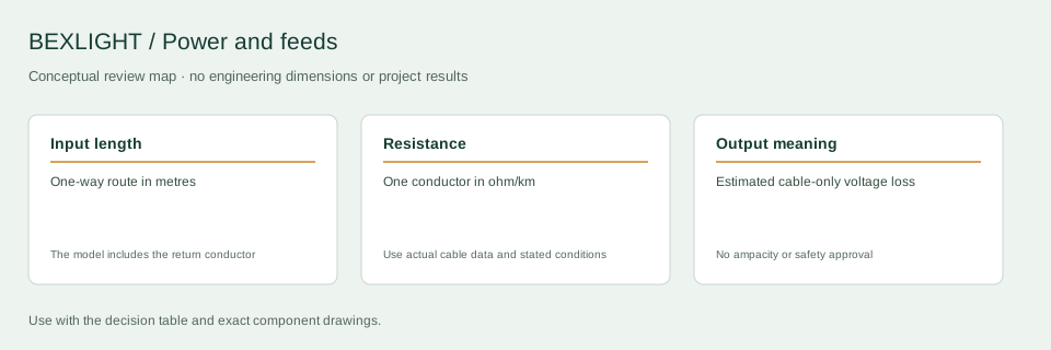
Decision and input record
| Decision | What to check | Record or boundary |
|---|---|---|
| Input length | One-way route in metres | The model includes the return conductor |
| Resistance | One conductor in ohm/km | Use actual cable data and stated conditions |
| Output meaning | Estimated cable-only voltage loss | No ampacity or safety approval |
Use the resistance for the actual cable
Obtain conductor resistance from the cable data sheet and note its stated conditions. Enter one-way route length, not the sum of outgoing and return lengths, when the formula already multiplies by two. If the conductors differ or the route branches, model the separate paths instead of forcing them into this simple equal-conductor calculation.
Worked example with declared assumptions
Assume a one-way length of 10 m, equal-conductor resistance of 8 ohm/km, 3 A DC current and a 24 V source. Loop resistance is 2 × 10 × 8 / 1000 = 0.16 ohm. Estimated drop is 3 × 0.16 = 0.48 V, or 2% of 24 V. Estimated cable dissipation is 3 × 3 × 0.16 = 1.44 W. All inputs are hypothetical; the result is not a rating for a named BEXLIGHT model or cable.
Decide what the answer does not cover
The calculation excludes connections and variation in conductor resistance with operating conditions. It does not predict brightness variation along the source, check ampacity, select protective devices or establish compliance. An acceptable voltage budget must come from the system design and source requirements. A low calculated percentage alone does not approve the installation.
Use the estimate to ask a better question
Compare realistic route alternatives or conductor data at the same design load. Identify which assumption dominates the result. Then ask the electrical designer to review the selected cable, routing and terminations against the installation conditions. If the design changes, update the load and path rather than reusing the old percentage.
Verify an installed section
Record measured source and load-end voltage under the defined operating scene using an appropriate measurement procedure. Keep the measurement locations with the drawing. If a dim end remains, investigate the strip and connections as separate sections of the circuit rather than attributing every loss to the feed cable.
What to include in a technical inquiry
Use the cable-drop worksheet to make assumptions visible, then include the route, cable data and design load with the electrical review.
Discuss the application and supply scope
Continue with the relevant detail
Tell us about your installation
Include the application, section lengths, quantity and installation conditions.
Discuss your requirement