

Power feeds for commercial cove lighting
Prepare a cove feed schedule from identified strip sections and actual component limits.
Updated October 26, 2026
Discuss your requirementOn this page
Prepare a cove feed schedule from identified strip sections and actual component limits. Neither reel length nor a generic “maximum run” table is enough to decide how a commercial installation should be divided.
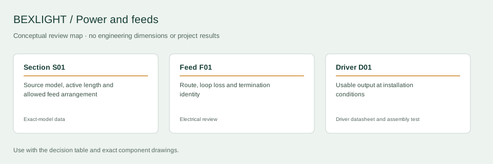
Decision and input record
| Decision | What to check | Record or boundary |
|---|---|---|
| Section S01 | Source model, active length and allowed feed arrangement | Exact-model data |
| Feed F01 | Route, loop loss and termination identity | Electrical review |
| Driver D01 | Usable output at installation conditions | Driver datasheet and assembly test |
Build the section schedule
For each section, record its code, active length, exact source model, voltage, rated power basis, proposed feed arrangement and control zone. Obtain the product-specific permitted run and feed information. Keep mechanically separate pieces identifiable even when the architect sees one continuous line.
Calculate the declared DC load
For a hypothetical uniform strip rated at 10 W/m, an 8 m total active length gives 80 W at the stated rating basis. At a nominal 24 V, the corresponding design-current arithmetic is 80/24 = 3.33 A. These are planning calculations, not measured BEXLIGHT product results. Use the source and controller documentation to determine the actual worst permitted operating scene.
Choose a capacity scenario explicitly
If a designer chooses an 80% utilization assumption, an 80 W load gives 80/0.8 = 100 W of scenario capacity. That assumption is not a universal driver rule. Check the exact driver’s temperature and input derating, output limits, installation requirements and startup behaviour. A controller or connector can remain a limiting component even when the driver has spare nameplate capacity.
Review the feed path separately
Record cable lengths and the relevant conductor resistance, then estimate loop loss. That calculation does not describe losses along the strip PCB or inside joints. Ask the electrical designer to review conductor suitability and protection. Do not join outputs from independent supplies or choose a two-end feed detail without an approved product-specific scheme.
Close the drawing loop
Label feeds and equipment access on the ceiling plan. Demonstrate the longest or otherwise demanding section in the installation geometry. Record supply conditions, visual observations and the manufacturer-required temperature checks. Keep the final schedule with the as-built controls and replacement instructions.
What to include in a technical inquiry
Send the route plan, section lengths and equipment locations. Open inputs such as driver enclosure temperature or an unconfirmed product run limit should stay visible in the schedule until resolved.
Discuss the application and supply scope
Continue with the relevant detail
- Cove lighting for commercial interiors
- DC cable voltage-drop planning
- Strip load and driver-capacity worksheet
Reference and scope
- MEAN WELL: driver application and operating-condition guidance. Driver-specific application reference; no BEXLIGHT product approval implied.
Tell us about your installation
Include the application, section lengths, quantity and installation conditions.
Discuss your requirement